
Page 177 - Satellite Communications, Fourth Edition
P. 177
Antennas 157
(a)
(b)
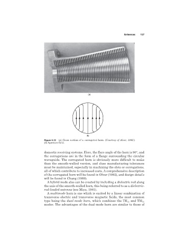
Figure 6.12 (a) Cross section of a corrugated horn. (Courtesy of Alver, 1992.)
(b) Aperture field.
domestic receiving systems. Here, the flare angle of the horn is 90°, and
the corrugations are in the form of a flange surrounding the circular
waveguide. The corrugated horn is obviously more difficult to make
than the smooth-walled version, and close manufacturing tolerances
must be maintained, especially in machining the slots or corrugations,
all of which contribute to increased costs. A comprehensive description
of the corrugated horn will be found in Olver (1992), and design details
will be found in Chang (1989).
A hybrid mode also can be created by including a dielectric rod along
the axis of the smooth-walled horn, this being referred to as a dielectric-
rod-loaded antenna (see Miya, 1981).
A multimode horn is one which is excited by a linear combination of
transverse electric and transverse magnetic fields, the most common
type being the dual-mode horn, which combines the TE 11 and TM 11
modes. The advantages of the dual-mode horn are similar to those of