
Page 346 - Satellite Communications, Fourth Edition
P. 346
326 Chapter Eleven
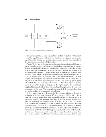
U1
Input Encoded
data S1 S2 S3 output
U2
Figure 11.2 A rate 1/2 convolutional encoder.
to its initial condition. The commutator at the output is switched at
twice the input bit rate so that two output bits are generated for each
input bit shifted in. At any one time the register holds 3 bits which form
the inputs to the exclusive-OR circuits.
Figure 11.3 is a tree diagram showing the changes in the shift regis-
ter as input is moved in, with the corresponding output shown in paren-
theses. At the initial condition, the register stores 000, and the output
is 00. If the first message bit in is a 1, the lower branch is followed, and
the output is seen to be 11. Continuing with this example, suppose that
the next three input bits are 001; then the corresponding output is 01
11 11. In other words, for an input 1001 (shown shaded in Fig. 11.3), the
output, including the initial condition (enclosed here in brackets), is
[00] 11 01 11 11. From this example it will be seen that any given input
bit contributes, for as long as it remains in the shift register, to the
encoded word. The number of stages in the register gives the constraint
length of the encoder. Denoting the constraint length by m, the encoder
is specified by (n, k, m). The example shows a (2, 1, 3) encoder. Encoders
are optimized through computer simulation.
At the receiver, the tree diagram for the encoder is known. Decoding
proceeds in the reverse manner. If, for example, [00] 11 01 11 11 is
received, the tree is searched for the matching branches, from which the
input can be deduced. Suppose, however, that an error occurs in trans-
mission, changing the received word to [00] 01 01 11 11; i.e., the error
is in the first bit following the initial condition. The receiver decoder
expects either a 00 or a 11 to follow the initial 00; therefore, it has to
make the assumption that an error has occurred. If it assumes that 00
was intended, it will follow the upper branch, but now a further diffi-
culty arises. The next possible pair is 00 or 11, neither of which matches
the received code word. On the other hand, if it assumes that 11 was