
Page 349 - Satellite Communications, Fourth Edition
P. 349
Error Control Coding 329
. . . b 1 b 2 b 3 . . . b 23 b 24 . . .
Time
(a)
Column No.
1 2 3 4 5 6
Row No.
1 b 24 b 23 b 22 b 21 b 20 b 19
2 b 18 b 17 b 16 b 15 b 14 b 13
3 b 12 b 11 b 10 b 9 b 8 b 7
4 b 6 b 5 b 4 b 3 b 2 b 1
5 c 1 c 4 c 7 c 10 c 13 c 16
6 c 2 c 5 c 8 c 11 c 14 c 17
7 c 3 c 6 c 9 c 12 c 15 b 18
(b)
Row 4
Row 7 Row 6 Row 5 Row 3 Row 2 Row 1
b 1 b 2 b 3 b 4 b 5 b 6
Time
(c)
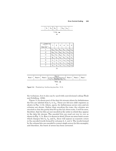
Figure 11.5 Illustrating interleaving (see Sec. 11.5).
the technique, but it also can be used with convolutional coding (Taub
and Schilling, 1986).
Figure 11.5a shows part of the data bit stream where for definiteness
the bits are labeled from b to b . These are fed into shift registers as
24
1
shown in Fig. 11.5b, where, again, for definiteness seven rows and six
columns are shown. Rather than encoding the rows, the columns are
encoded so that the parity bits fill up the last three rows. It will be seen,
therefore, that the bits are not encoded in the order in which they appear
in the data bit stream. The encoded bits are read out row by row as
shown in Fig. 11.5c. Row 4 is shown in detail. If now an error burst occurs
which changes bits b ,b , and b , these will appear as separate errors
3
5
4
in the encoded words formed by columns 2, 3, and 4. The words formed
by the column bits are encoded to correct single errors (in this example),
and therefore, the burst of errors has been corrected.