
Page 103 - Schaum's Outline of Theory and Problems of Electric Circuits
P. 103
AMPLIFIERS AND OPERATIONAL AMPLIFIER CIRCUITS
92
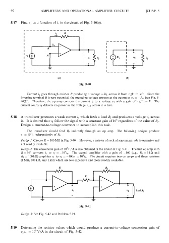
5.17 Find v 2 as a function of i 1 in the circuit of Fig. 5-40(a). [CHAP. 5
Fig. 5-40
Current i 1 goes through resistor R producing a voltage Ri 1 across it from right to left. Since the
inverting terminal B is zero potential, the preceding voltage appears at the output as v 2 ¼ Ri 1 [see Fig. 5-
40(b)]. Therefore, the op amp converts the current i 1 to a voltage v 2 with a gain of jv 2 =i 1 j¼ R. The
current source i 1 delivers no power as the voltage v AB across it is zero.
5.18 A transducer generates a weak current i 1 which feeds a load R l and produces a voltage v 1 across
8
it. It is desired that v 1 follow the signal with a constant gain of 10 regardless of the value of R l .
Design a current-to-voltage converter to accomplish this task.
The transducer should feed R l indirectly through an op amp. The following designs produce
8
v 1 ¼ 10 i 1 independently of R l .
Design 1: Choose R ¼ 100 M
in Fig. 5-40. However, a resistor of such a large magnitude is expensive and
not readily available.
8
Design 2: The conversion gain of 10 V=A is also obtained in the circuit of Fig. 5-41. The first op amp with
6
6
R ¼ 10 converts i 1 to v 1 ¼ 10 i 1 . The second amplifier with a gain of 100 (e.g., R 1 ¼ 1k
and
8
R 2 ¼ 100 k
) amplifies v 1 to v 2 ¼ 100v 1 ¼ 10 i 1 . The circuit requires two op amps and three resistors
(1 M
, 100 k
, and 1 k
) which are less expensive and more readily available.
Fig. 5-41
Design 3: See Fig. 5-42 and Problem 5.19.
5.19 Determine the resistor values which would produce a current-to-voltage conversion gain of
8
v 2 =i 1 ¼ 10 V=A in the circuit of Fig. 5-42.