
Page 104 - Schaum's Outline of Theory and Problems of Electric Circuits
P. 104
AMPLIFIERS AND OPERATIONAL AMPLIFIER CIRCUITS
CHAP. 5]
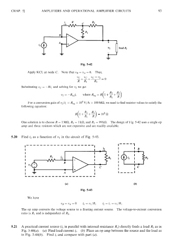
Fig. 5-42 93
Apply KCL at node C. Note that v B ¼ v A ¼ 0. Thus,
v C v C v C v 2
þ þ ¼ 0
R R 1 R 2
Substituting v C ¼ Ri 1 and solving for v 2 we get
R 2 R 2
where R eq ¼ R 1 þ þ
v 2 ¼ R eq i 1
R 1 R
8
For a conversion gain of v 2 =i 1 ¼ R eq ¼ 10 V=A ¼ 100 M
, we need to find resistor values to satisfy the
following equation:
R 2 R 2 8
R 1 þ þ ¼ 10
R 1 R
One solution is to choose R ¼ 1M
, R 1 ¼ 1k
, and R 2 ¼ 99 k
. The design of Fig. 5-42 uses a single op
amp and three resistors which are not expensive and are readily available.
5.20 Find i 2 as a function of v 1 in the circuit of Fig. 5-43.
Fig. 5-43
We have
v B ¼ v A ¼ 0 i 1 ¼ v 1 =R 1 i 2 ¼ i 1 ¼ v 1 =R 1
The op amp converts the voltage source to a floating current source. The voltage-to-current conversion
ratio is R 1 and is independent of R 2 .
5.21 A practical current source (i s in parallel with internal resistance R s ) directly feeds a load R l as in
Fig. 5-44(a). (a) Find load current i .(b) Place an op amp between the source and the load as
l
in Fig. 5-44(b). Find i l and compare with part (a).