
Page 108 - Schaum's Outline of Theory and Problems of Electric Circuits
P. 108
97
AMPLIFIERS AND OPERATIONAL AMPLIFIER CIRCUITS
CHAP. 5]
The circuit of Fig. 5-49 has an infinite input resistance, employs resistors within ordinary range, and
uses three op amps.
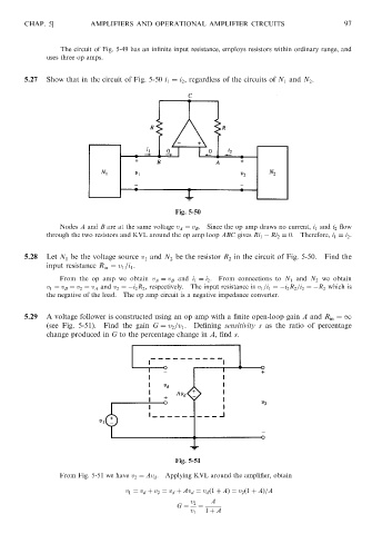
5.27 Show that in the circuit of Fig. 5-50 i 1 ¼ i 2 , regardless of the circuits of N 1 and N 2 .
Fig. 5-50
Nodes A and B are at the same voltage v A ¼ v B . Since the op amp draws no current, i 1 and i 2 flow
through the two resistors and KVL around the op amp loop ABC gives Ri 1 Ri 2 ¼ 0. Therefore, i 1 ¼ i 2 .
5.28 Let N 1 be the voltage source v 1 and N 2 be the resistor R 2 in the circuit of Fig. 5-50. Find the
input resistance R in ¼ v 1 =i 1 .
From the op amp we obtain v A ¼ v B and i 1 ¼ i 2 . From connections to N 1 and N 2 we obtain
v 1 ¼ v B ¼ v 2 ¼ v A and v 2 ¼ i 2 R 2 , respectively. The input resistance is v 1 =i 1 ¼ i 2 R 2 =i 2 ¼ R 2 which is
the negative of the load. The op amp circuit is a negative impedance converter.
5.29 A voltage follower is constructed using an op amp with a finite open-loop gain A and R in ¼1
(see Fig. 5-51). Find the gain G ¼ v 2 =v 1 . Defining sensitivity s as the ratio of percentage
change produced in G to the percentage change in A, find s.
Fig. 5-51
From Fig. 5-51 we have v 2 ¼ Av d . Applying KVL around the amplifier, obtain
v 1 ¼ v d þ v 2 ¼ v d þ Av d ¼ v d ð1 þ AÞ¼ v 2 ð1 þ AÞ=A
A
v 2
G ¼ ¼
v 1 1 þ A