
Page 110 - Schaum's Outline of Theory and Problems of Electric Circuits
P. 110
AMPLIFIERS AND OPERATIONAL AMPLIFIER CIRCUITS
99
CHAP. 5]
5.34 In the circuit of Fig. 5-13, V cc ¼ 10 V, R 1 ¼ 2k
and v 1 ¼ 1 V. Find the maximum value of R 2 before the
op amp is saturated. Ans: R 2 ¼ 20 k
5.35 Let the summing circuit of Fig. 5-14 have two inputs with v 1 ¼ 1 and v 2 ¼ sin t (V). Let R 1 ¼ 3k
,
8
8
R 2 ¼ 5k
, and R f ¼ 8k
. Apply superposition to find v o . Ans: v o ¼ ð þ sin tÞ
3 5
5.36 In Fig. 5-17 let R 1 ¼ 4k
and R 2 ¼ 8k
. Apply superposition to find v o in terms of the input voltages.
Ans: v o ¼ v 1 þ v 2 þ v 3
5.37 Find the input resistance seen by v f in Fig. 5-19. Ans: R in ¼ 2R 1
5.38 Use superposition to find v o in Fig. 5-20 for R 1 ¼ 2, R 2 ¼ 7, R 3 ¼ 10, R 4 ¼ 5, all values in k
.
Ans: v o ¼ 1:5v 2 3:5v 1
5.39 In the circuit of Fig. 5-20 find (a) v 0 for R 1 ¼ 1, R 2 ¼ 3, R 3 ¼ 2, and R 4 ¼ 2, all values in k
; (b) the input
resistance R 2in seen by v 2 ; (c) i 1 as a function of v 1 and v 2 and show that v 1 sees a variable load which
depends on v 2 . Ans: ðaÞ v o ¼ 2v 2 3v 1 ; ðbÞ R 2in ¼ 4k
; ðcÞ i 1 ¼ v 1 v 2 =2
5.40 Using a single op amp, design an amplifier with a gain of v 2 =v 1 ¼ 3=4, input resistance of 8 k
, and zero
output resistance. Ans: See Fig. 5-53.
Fig. 5-53
5.41 Show that, given R 1 ¼1 and R 2 ¼ 0, the noninverting op amp circuit of Fig. 5-15 and (12) is reduced to a
voltage follower.
5.42 In the circuit of Fig. 5-22 let R s ¼ 10 k
. (a) Find R f such that i s ¼ 0. (b)Is R f independent of R s ?
Discuss. Ans: ðaÞ 40 k
; ðbÞ yes
5.43 The input to the circuit of Fig. 5-23 with RC ¼ 1is v 1 ¼ sin !t. Write KCL at node B and solve for v 2 .
Ans: v 2 ¼ ð1=!Þ cos !t þ C
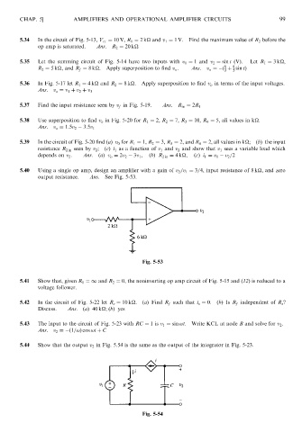
5.44 Show that the output v 2 in Fig. 5.54 is the same as the output of the integrator in Fig. 5-23.
Fig. 5-54