
Page 105 - Schaum's Outline of Theory and Problems of Electric Circuits
P. 105
AMPLIFIERS AND OPERATIONAL AMPLIFIER CIRCUITS
94
Fig. 5-44 [CHAP. 5
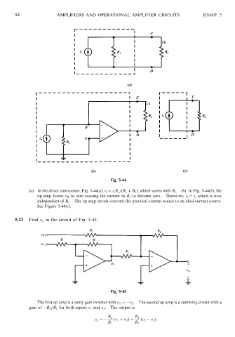
(a) In the direct connection, Fig. 5-44(a), i l ¼ i s R s =ðR s þ R l Þ, which varies with R l .(b) In Fig. 5-44(b), the
op amp forces v B to zero causing the current in R s to become zero. Therefore, i l ¼ i s which is now
independent of R l . The op amp circuit converts the practical current source to an ideal current source.
See Figure 5-44(c).
5.22 Find v o in the circuit of Fig. 5-45.
Fig. 5-45
The first op amp is a unity gain inverter with v 3 ¼ v 2 . The second op amp is a summing circuit with a
gain of R 2 =R 1 for both inputs v 1 and v 3 . The output is
R 2 R 2
v o ¼ ðv 1 þ v 3 Þ¼ ðv 2 v 1 Þ
R 1 R 1