
Page 150 - Schaum's Outline of Theory and Problems of Electric Circuits
P. 150
FIRST-ORDER CIRCUITS
CHAP. 7]
7.10 RESPONSE OF FIRST-ORDER CIRCUITS TO A PULSE 139
In this section we will derive the response of a first-order circuit to a rectangular pulse. The
derivation applies to RC or RL circuits where the input can be a current or a voltage. As an example,
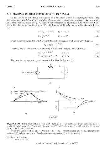
we use the series RC circuit in Fig. 7-17(a) with the voltage source delivering a pulse of duration T and
height V 0 . For t < 0, v and i are zero. For the duration of the pulse, we use (6b) and (6c) in Section
7.3:
v ¼ V 0 ð1 e t=RC Þ ð0 < t < TÞ ð14aÞ
V 0 t=RC
i ¼ e ð0 < t < TÞ ð14bÞ
R
When the pulse ceases, the circuit is source-free with the capacitor at an initial voltage V T .
V T ¼ V 0 ð1 e T=RC Þ ð14cÞ
Using (3) and (4) in Section 7.2, and taking into account the time shift T, we have
v ¼ V T e ðt TÞ=RC ðt > TÞ ð15aÞ
ðt TÞ=RC
i ¼ ðV T =RÞe ðt > TÞ ð15bÞ
The capacitor voltage and current are plotted in Figs. 7-17(b) and (c).
Fig. 7-17
EXAMPLE 7.11 In the circuit of Fig. 7-17(a), let R ¼ 1k
and C ¼ 1 mF and let the voltage source be a pulse of
height V 0 and duration T. Find i and v for (a) V 0 ¼ 1 V and T ¼ 1 ms, (b) V 0 ¼ 10 V and T ¼ 0:1 ms, and
(c) V 0 ¼ 100 V and T ¼ 0:01 ms.
We use (14) and (15) with the time constant of ¼ RC ¼ 1 ms. For convenience, time will be expressed in ms,
voltages in V, and currents in mA. We also use the approximation e t ¼ 1 t when t 1.
(a) V 0 ¼ 1V, T ¼ 1 ms.
For 0 < t < 1 ms,
1
t
t
v ¼ð1 e Þ; i ¼ e , and V T ¼ð1 e Þ¼ 0:632 V