
Page 155 - Schaum's Outline of Theory and Problems of Electric Circuits
P. 155
FIRST-ORDER CIRCUITS
144
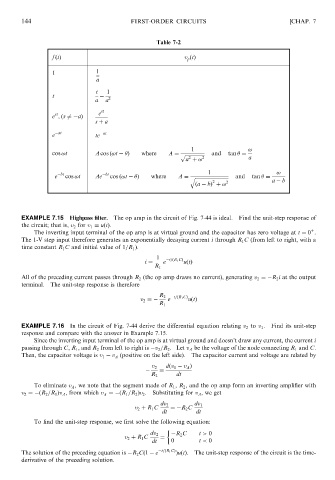
Table 7-2 [CHAP. 7
f ðtÞ v p ðtÞ
1 1
a
t 1
t
a a 2
st
e ; ðs 6¼ aÞ e st
s þ a
at at
e te
1 !
cos !t A cos ð!t Þ where A ¼ p ffiffiffiffiffiffiffiffiffiffiffiffiffiffiffiffi and tan ¼
2
a þ ! 2 a
bt bt 1 !
e cos !t Ae cos ð!t Þ where A ¼ q ffiffiffiffiffiffiffiffiffiffiffiffiffiffiffiffiffiffiffiffiffiffiffiffiffiffiffi and tan ¼
2
ða bÞ þ ! 2 a b
EXAMPLE 7.15 Highpass filter. The op amp in the circuit of Fig. 7-44 is ideal. Find the unit-step response of
the circuit; that is, v 2 for v 1 ¼ uðtÞ:
þ
The inverting input terminal of the op amp is at virtual ground and the capacitor has zero voltage at t ¼ 0 .
The 1-V step input therefore generates an exponentially decaying current i through R 1 C (from left to right, with a
time constant R 1 C and initial value of 1=R 1 ).
1
i ¼ e t=ðR 1 CÞ uðtÞ
R 1
All of the preceding current passes through R 2 (the op amp draws no current), generating v 2 ¼ R 2 i at the output
terminal. The unit-step response is therefore
R 2 t=ðR 1 CÞ
v 2 ¼ e uðtÞ
R 1
EXAMPLE 7.16 In the circuit of Fig. 7-44 derive the differential equation relating v 2 to v 1 . Find its unit-step
response and compare with the answer in Example 7.15.
Since the inverting input terminal of the op amp is at virtual ground and doesn’t draw any current, the current i
passing through C, R 1 , and R 2 from left to right is v 2 =R 2 . Let v A be the voltage of the node connecting R 1 and C.
Then, the capacitor voltage is v 1 v A (positive on the left side). The capacitor current and voltage are related by
v 2 dðv 1 v A Þ
¼
R 2 dt
To eliminate v A , we note that the segment made of R 1 , R 2 , and the op amp form an inverting amplifier with
v 2 ¼ ðR 2 =R 1 Þv A , from which v A ¼ ðR 1 =R 2 Þv 2 . Substituting for v A , we get
dv 2 dv 1
v 2 þ R 1 C ¼ R 2 C
dt dt
To find the unit-step response, we first solve the following equation:
dv 2 R 2 C t > 0
v 2 þ R 1 C ¼
dt 0 t < 0
The solution of the preceding equation is R 2 Cð1 e t=ðR 1 CÞ ÞuðtÞ. The unit-step response of the circuit is the time-
derivative of the preceding solution.