
Page 158 - Schaum's Outline of Theory and Problems of Electric Circuits
P. 158
FIRST-ORDER CIRCUITS
147
CHAP. 7]
7.6 A series RC circuit with R ¼ 5k
and C ¼ 20 mF has a constant-voltage source of 100 V applied
at t ¼ 0; there is no initial charge on the capacitor. Obtain i, v R , v C , and q, for t > 0.
The capacitor charge, and hence v C , must be continuous at t ¼ 0:
þ
v C ð0 Þ¼ v C ð0 Þ¼ 0
As t !1, v C ! 100 V, the applied voltage. The time constant of the circuit is ¼ RC ¼ 10 1 s. Hence,
from Section 6.10,
þ
v C ¼½v C ð0 Þ v C ð1Þe t= þ v C ð1Þ ¼ 100e 10t þ 100 ðVÞ
The other functions follow from this. If the element voltages are both positive where the current
enters, v R þ v C ¼ 100 V, and so
v R ¼ 100e 10t ðVÞ
v R 10t
i ¼ ¼ 20e ðmAÞ
R
q ¼ Cv C ¼ 2000ð1 e 10t Þ ðmCÞ
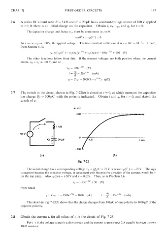
7.7 The switch in the circuit shown in Fig. 7-22(a) is closed at t ¼ 0, at which moment the capacitor
has charge Q ¼ 500 mC, with the polarity indicated. Obtain i and q, for t > 0, and sketch the
0
graph of q.
Fig. 7-22
þ
The initial charge has a corresponding voltage V 0 ¼ Q 0 =C ¼ 25 V, whence v C ð0 Þ¼ 25 V. The sign
is negative because the capacitor voltage, in agreement with the positive direction of the current, would be þ
on the top plate. Also v C ð1Þ ¼ þ50 V and ¼ 0:02 s. Thus, as in Problem 7.6,
v C ¼ 75e 50t þ 50 ðVÞ
from which
dq
q ¼ Cv C ¼ 1500e 50t þ 1000 ðmCÞ i ¼ ¼ 75e 50t ðmAÞ
dt
The sketch in Fig. 7-22(b) shows that the charge changes from 500 mC of one polarity to 1000 mC of the
opposite polarity.
7.8 Obtain the current i, for all values of t, in the circuit of Fig. 7-23.
For t < 0, the voltage source is a short circuit and the current source shares 2 A equally between the two
10-
resistors: