Page 163 - Schaum's Outline of Theory and Problems of Electric Circuits
P. 163

FIRST-ORDER CIRCUITS
                                                                                                [CHAP. 7
               152
               7.16  In the circuit shown in Fig. 7-30, the switch is moved to position 2 at t ¼ 0.  Obtain the current i 2
                     at t ¼ 34:7 ms.
                         After the switching, the three inductances have the equivalent
                                                          10  5ð10Þ
                                                     L eq ¼  þ     ¼ 5H
                                                           6   15
                     Then   ¼ 5=200 ¼ 25 ms, and so, with t in ms,

                                                                  5
                                            i ¼ 6e  t=25  ðAÞ  i 2 ¼  i ¼ 2e  t=25  ðAÞ
                                                                  15
                     and                           i 2 ð34:7Þ¼ 2e  34:7=25  A ¼ 0:50 A


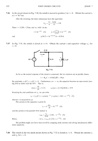
               7.17  In Fig. 7-31, the switch is closed at t ¼ 0.  Obtain the current i and capacitor voltage v C , for
                     t > 0.


                                                        Fig. 7-31
                         As far as the natural response of the circuit is concerned, the two resistors are in parallel; hence,
                                                    ¼ R eq C ¼ð5 
Þð2 mFÞ¼ 10 ms


                                    þ
                     By continuity, v C ð0 Þ¼ v C ð0 Þ¼ 0. Furthermore, as t !1, the capacitor becomes an open circuit, leav-
                     ing 20 
 in series with the 50 V.  That is,
                                               50
                                         ið1Þ ¼  ¼ 2:5A      v C ð1Þ ¼ ð2:5AÞð10 
Þ¼ 25 V
                                               20
                     Knowing the end conditions on v C , we can write
                                                þ
                                        v C ¼½v C ð0 Þ  v C ð1ފe  t=   þ v C ð1Þ ¼ 25ð1   e  t=10 Þ  ðVÞ
                     wherein t is measured in ms.
                         The current in the capacitor is given by

                                                          dv C    t=10
                                                    i C ¼ C  ¼ 5e     ðAÞ
                                                           dt
                     and the current in the parallel 10-
 resistor is
                                                       v C          t=10
                                                 i 10
 ¼  ¼ 2:5ð1   e  Þ  ðAÞ
                                                       10
                     Hence,                      i ¼ i C þ i 10 
 ¼ 2:5ð1 þ e  t=10 ÞðAÞ
                         The problem might also have been solved by assigning mesh currents and solving simultaneous differ-
                     ential equations.


               7.18  The switch in the two-mesh circuit shown in Fig. 7-32 is closed at t ¼ 0.  Obtain the currents i 1
                     and i 2 , for t > 0.
   158   159   160   161   162   163   164   165   166   167   168