Page 162 - Schaum's Outline of Theory and Problems of Electric Circuits
P. 162

FIRST-ORDER CIRCUITS
               CHAP. 7]
                                                              25   3:46                              151
                                                    t 2   t 1
                                                 ¼         ¼          ¼ 15:54 ms
                                                  ln v 1   ln v 2  ln 20   ln 5
                                                      L       2
                     and so                       R ¼  ¼            ¼ 128:7
                                                         15:54   10  3

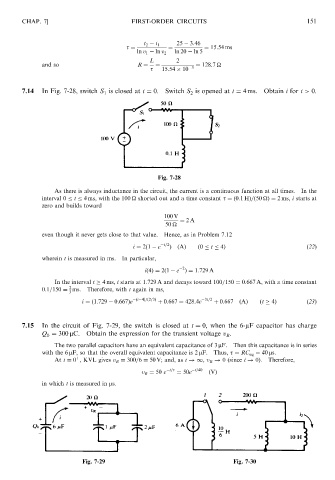
               7.14  In Fig. 7-28, switch S 1 is closed at t ¼ 0.  Switch S 2 is opened at t ¼ 4 ms.  Obtain i for t > 0.


                                                        Fig. 7-28

                         As there is always inductance in the circuit, the current is a continuous function at all times. In the
                     interval 0   t   4 ms, with the 100 
 shorted out and a time constant   ¼ð0:1HÞ=ð50 
Þ¼ 2 ms, i starts at
                     zero and builds toward
                                                          100 V
                                                               ¼ 2A
                                                          50
                     even though it never gets close to that value.  Hence, as in Problem 7.12
                                                 i ¼ 2ð1   e  t=2 Þ  ðAÞ  ð0   t   4Þ                ð22Þ
                     wherein t is measured in ms.  In particular,
                                                                2
                                                    ið4Þ¼ 2ð1   e Þ¼ 1:729 A
                         In the interval t   4 ms, i starts at 1.729 A and decays toward 100=150 ¼ 0:667 A, with a time constant
                              2
                     0:1=150 ¼ ms.  Therefore, with t again in ms,
                              3
                                 i ¼ð1:729   0:667Þe  ðt 4Þ=ð2=3Þ  þ 0:667 ¼ 428:4e  3t=2  þ 0:667  ðAÞ  ðt   4Þ  ð23Þ


               7.15  In the circuit of Fig. 7-29, the switch is closed at t ¼ 0, when the 6-mF capacitor has charge
                     Q 0 ¼ 300 mC. Obtain the expression for the transient voltage v R .
                         The two parallel capacitors have an equivalent capacitance of 3 mF. Then this capacitance is in series
                     with the 6 mF, so that the overall equivalent capacitance is 2 mF. Thus,   ¼ RC eq ¼ 40 ms.
                                þ
                         At t ¼ 0 , KVL gives v R ¼ 300=6 ¼ 50 V; and, as t !1, v R ! 0 (since i ! 0).  Therefore,
                                                            t=     t=40
                                                   v R ¼ 50 e  ¼ 50e   ðVÞ
                     in which t is measured in ms.


                                 Fig. 7-29                                     Fig. 7-30
   157   158   159   160   161   162   163   164   165   166   167