Page 156 - Schaum's Outline of Theory and Problems of Electric Circuits
P. 156

FIRST-ORDER CIRCUITS
               CHAP. 7]
                                                          R 2   t=ðR 1 CÞ                            145
                                                  v 2 ðtÞ¼    e   uðtÞ
                                                          R 1
               Alternate Approach
                   The unit step response may also be found by the Laplace transform method (see Chapter 16).

               EXAMPLE 7.17   Passive phase shifter.  Find the relationship between v 2 and v 1 in the circuit of Fig. 7-45(a).
                   Let node D be the reference node.  Apply KCL at nodes A and B to find
                                                                  ðv A   v 1 Þ
                                                             dv A
                                           KCL at node A:  C    þ         ¼ 0
                                                              dt     R
                                                             dðv B   v 1 Þ  v B
                                           KCL at node B:  C         þ    ¼ 0
                                                                dt     R
                   Subtracting the second equation from the first and noting that v 2 ¼ v A   v B we get
                                                        dv 2        dv 1
                                                 v 2 þ RC  ¼ v 1   RC
                                                        dt          dt
               EXAMPLE 7.18   Active phase shifter. Show that the relationship between v 2 and v 1 in the circuit of Fig. 7-45(b)is
               the same as in Fig. 7-45(a).
                   Apply KCL at the inverting (node A) and non-inverting (node B) inputs of the op amp.
                                                          ðv A   v 1 Þ  ðv A   v 2 Þ
                                          KCL at node A:          þ        ¼ 0
                                                             R 1      R 1
                                                          ðv B   v 1 Þ  dv B
                                          KCL at node B:          þ C   ¼ 0
                                                             R        dt
               From the op amp we have v A ¼ v B and from the KCL equation for node A, we have v A ¼ðv 1 þ v 2 Þ=2.  Substituting
               the preceding values in the KCL at node B, we find

                                                        dv 2        dv 1
                                                 v 2 þ RC  ¼ v 1   RC
                                                        dt          dt


                                                  Solved Problems


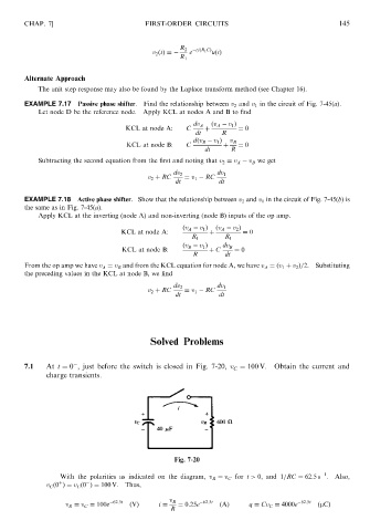
               7.1   At t ¼ 0 , just before the switch is closed in Fig. 7-20, v ¼ 100 V.  Obtain the current and
                                                                        C
                     charge transients.


                                                        Fig. 7-20

                                                                                                 1
                         With the polarities as indicated on the diagram, v R ¼ v C for t > 0, and 1=RC ¼ 62:5s .  Also,

                         þ
                     v C ð0 Þ¼ v C ð0 Þ¼ 100 V. Thus,
                           v R ¼ v C ¼ 100e  62:5t  ðVÞ  i ¼  v R  ¼ 0:25e  62:5t  ðAÞ  q ¼ Cv C ¼ 4000e  62:5t  ðmCÞ
                                                       R
   151   152   153   154   155   156   157   158   159   160   161