
Page 18 - Schaum's Outline of Theory and Problems of Electric Circuits
P. 18
Circuit Concepts
2.1 PASSIVE AND ACTIVE ELEMENTS
An electrical device is represented by a circuit diagram or network constructed from series and
parallel arrangements of two-terminal elements. The analysis of the circuit diagram predicts the perfor-
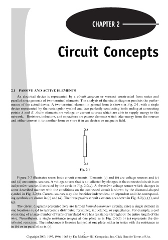
mance of the actual device. A two-terminal element in general form is shown in Fig. 2-1, with a single
device represented by the rectangular symbol and two perfectly conducting leads ending at connecting
points A and B. Active elements are voltage or current sources which are able to supply energy to the
network. Resistors, inductors, and capacitors are passive elements which take energy from the sources
and either convert it to another form or store it in an electric or magnetic field.
Fig. 2-1
Figure 2-2 illustrates seven basic circuit elements. Elements (a) and (b) are voltage sources and (c)
and (d) are current sources. A voltage source that is not affected by changes in the connected circuit is an
independent source, illustrated by the circle in Fig. 2-2(a). A dependent voltage source which changes in
some described manner with the conditions on the connected circuit is shown by the diamond-shaped
symbol in Fig. 2-2(b). Current sources may also be either independent or dependent and the correspond-
ing symbols are shown in (c) and (d). The three passive circuit elements are shown in Fig. 2-2(e), ( f ), and
(g).
The circuit diagrams presented here are termed lumped-parameter circuits, since a single element in
one location is used to represent a distributed resistance, inductance, or capacitance. For example, a coil
consisting of a large number of turns of insulated wire has resistance throughout the entire length of the
wire. Nevertheless, a single resistance lumped at one place as in Fig. 2-3(b)or(c) represents the dis-
tributed resistance. The inductance is likewise lumped at one place, either in series with the resistance as
in (b) or in parallel as in (c).
7
Copyright 2003, 1997, 1986, 1965 by The McGraw-Hill Companies, Inc. Click Here for Terms of Use.