
Page 23 - Schaum's Outline of Theory and Problems of Electric Circuits
P. 23
12
2.6 CAPACITANCE CIRCUIT CONCEPTS [CHAP. 2
The circuit element that stores energy in an electric field is a capacitor (also called capacitance).
When the voltage is variable over a cycle, energy will be stored during one part of the cycle and
returned in the next. While an inductance cannot retain energy after removal of the source because the
magnetic field collapses, the capacitor retains the charge and the electric field can remain after the
source is removed. This charged condition can remain until a discharge path is provided, at which
time the energy is released. The charge, q ¼ Cv, on a capacitor results in an electric field in the
dielectric which is the mechanism of the energy storage. In the simple parallel-plate capacitor there
is an excess of charge on one plate and a deficiency on the other. It is the equalization of these charges
that takes place when the capacitor is discharged. The power and energy relationships for the capa-
citance are as follows.
dv d 1 2
p ¼ vi ¼ Cv ¼ Cv
dt dt 2
ð ð
t 2 t 2 1
2
2
w C ¼ pdt ¼ Cv dv ¼ C½v 2 v 1
2
t 1 t 1
2
1
The energy stored in the electric field of capacitance is w C ¼ Cv .
2
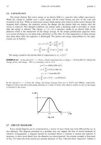
EXAMPLE 2.3. In the interval 0 > t > 5 ms, a 20-mF capacitance has a voltage v ¼ 50:0 sin 200t (V). Obtain the
charge, power, and energy. Plot w C assuming w ¼ 0at t ¼ 0.
q ¼ Cv ¼ 1000 sin 200t ðmCÞ
dv
i ¼ C ¼ 0:20 cos 200t ðAÞ
dt
p ¼ vi ¼ 5:0 sin 400t ðWÞ
ð
t 2
w C ¼ pdt ¼ 12:5½1 cos 400tðmJÞ
t 1
In the interval 0 > t > 2:5 ms the voltage and charge increase from zero to 50.0 V and 1000 mC, respectively.
Figure 2-8 shows that the stored energy increases to a value of 25 mJ, after which it returns to zero as the energy
is returned to the source.
Fig. 2-8
2.7 CIRCUIT DIAGRAMS
Every circuit diagram can be constructed in a variety of ways which may look different but are in
fact identical. The diagram presented in a problem may not suggest the best of several methods of
solution. Consequently, a diagram should be examined before a solution is started and redrawn if
necessary to show more clearly how the elements are interconnected. An extreme example is illustrated
in Fig. 2-9, where the three circuits are actually identical. In Fig. 2-9(a) the three ‘‘junctions’’ labeled A