
Page 24 - Schaum's Outline of Theory and Problems of Electric Circuits
P. 24
13
CIRCUIT CONCEPTS
CHAP. 2]
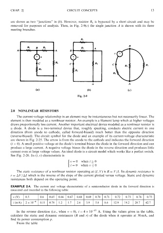
are shown as two ‘‘junctions’’ in (b). However, resistor R 4 is bypassed by a short circuit and may be
removed for purposes of analysis. Then, in Fig. 2-9(c) the single junction A is shown with its three
meeting branches.
Fig. 2-9
2.8 NONLINEAR RESISTORS
The current-voltage relationship in an element may be instantaneous but not necessarily linear. The
element is then modeled as a nonlinear resistor. An example is a filament lamp which at higher voltages
draws proportionally less current. Another important electrical device modeled as a nonlinear resistor is
a diode. A diode is a two-terminal device that, roughly speaking, conducts electric current in one
direction (from anode to cathode, called forward-biased) much better than the opposite direction
(reverse-biased). The circuit symbol for the diode and an example of its current-voltage characteristic
are shown in Fig. 2-25. The arrow is from the anode to the cathode and indicates the forward direction
ði > 0Þ. A small positive voltage at the diode’s terminal biases the diode in the forward direction and can
produce a large current. A negative voltage biases the diode in the reverse direction and produces little
current even at large voltage values. An ideal diode is a circuit model which works like a perfect switch.
See Fig. 2-26. Its ði; vÞ characteristic is
v ¼ 0 when i 0
i ¼ 0 when v 0
The static resistance of a nonlinear resistor operating at ðI; VÞ is R ¼ V=I. Its dynamic resistance is
r ¼ V= I which is the inverse of the slope of the current plotted versus voltage. Static and dynamic
resistances both depend on the operating point.
EXAMPLE 2.4. The current and voltage characteristic of a semiconductor diode in the forward direction is
measured and recorded in the following table:
v (V) 0.5 0.6 0.65 0.66 0.67 0.68 0.69 0.70 0.71 0.72 0.73 0.74 0.75
4
i (mA) 2 10 0.11 0.78 1.2 1.7 2.6 3.9 5.8 8.6 12.9 19.2 28.7 42.7
15
In the reverse direction (i.e., when v < 0), i ¼ 4 10 A. Using the values given in the table,
calculate the static and dynamic resistances (R and r) of the diode when it operates at 30 mA, and
find its power consumption p.
From the table