
Page 19 - Schaum's Outline of Theory and Problems of Electric Circuits
P. 19
CIRCUIT CONCEPTS
8
Fig. 2-2 [CHAP. 2
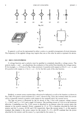
Fig. 2-3
In general, a coil can be represented by either a series or a parallel arrangement of circuit elements.
The frequency of the applied voltage may require that one or the other be used to represent the device.
2.2 SIGN CONVENTIONS
A voltage function and a polarity must be specified to completely describe a voltage source. The
polarity marks, þ and , are placed near the conductors of the symbol that identifies the voltage source.
If, for example, v ¼ 10:0 sin !t in Fig. 2-4(a), terminal A is positive with respect to B for 0 >!t > , and
B is positive with respect to A for >!t > 2 for the first cycle of the sine function.
Fig. 2-4
Similarly, a current source requires that a direction be indicated, as well as the function, as shown in
Fig. 2-4(b). For passive circuit elements R, L, and C, shown in Fig. 2-4(c), the terminal where the current
enters is generally treated as positive with respect to the terminal where the current leaves.
The sign on power is illustrated by the dc circuit of Fig. 2-5(a) with constant voltage sources
V A ¼ 20:0 V and V B ¼ 5:0 V and a single 5-
resistor. The resulting current of 3.0 A is in the clockwise
direction. Considering now Fig. 2-5(b), power is absorbed by an element when the current enters the
2
element at the positive terminal. Power, computed by VI or I R, is therefore absorbed by both the
resistor and the V B source, 45.0 W and 15 W respectively. Since the current enters V A at the negative
terminal, this element is the power source for the circuit. P ¼ VI ¼ 60:0 W confirms that the power
absorbed by the resistor and the source V B is provided by the source V A .