
Page 203 - Schaum's Outline of Theory and Problems of Electric Circuits
P. 203
SINUSOIDAL STEADY-STATE CIRCUIT ANALYSIS
[CHAP. 9
192
A comparison of v L and i shows that the current lags the voltage by 908 or =2 rad. The functions
are sketched in Fig. 9-1(b). Note that the current function i is to the right of v, and since the horizontal
scale is !t, events displaced to the right occur later in time. This illustrates that i lags v. The horizontal
scale is in radians, but note that it is also marked in degrees ( 1358; 1808, etc.). This is a case of mixed
units just as with !t þ 458. It is not mathematically correct but is the accepted practice in circuit
analysis. The vertical scale indicates two different quantities, that is, v and i, so there should be two
scales rather than one.
While examining this sketch, it is a good time to point out that a sinusoid is completely defined when
its magnitude ðV or IÞ, frequency (! or f ), and phase (458 or 1358) are specified.
In Table 9-1 the responses of the three basic circuit elements are shown for applied current
i ¼ I cos !t and voltage v ¼ V cos !t. If sketches are made of these responses, they will show that
for a resistance R, v and i are in phase. For an inductance L, i lags v by 908 or =2 rad. And for a
capacitance C, i leads v by 908 or =2 rad.
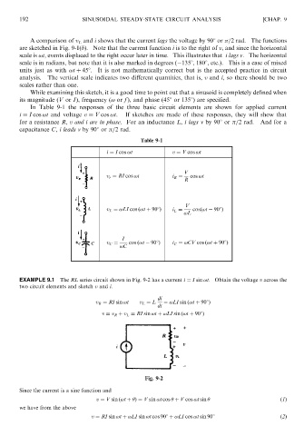
Table 9-1
i ¼ I cos !t v ¼ V cos !t
V
v r ¼ RI cos !t i R ¼ cos !t
R
V
v L ¼ !LI cos ð!t þ 908Þ i L ¼ cosð!t 908Þ
!L
I
v C ¼ cos ð!t 908Þ i C ¼ !CV cos ð!t þ 908Þ
!C
EXAMPLE 9.1 The RL series circuit shown in Fig. 9-2 has a current i ¼ I sin !t. Obtain the voltage v across the
two circuit elements and sketch v and i.
di
v R ¼ RI sin !t v L ¼ L ¼ !LI sin ð!t þ 908Þ
dt
v ¼ v R þ v L ¼ RI sin !t þ !LI sin ð!t þ 908Þ
Fig. 9-2
Since the current is a sine function and
v ¼ V sin ð!t þ Þ¼ V sin !t cos þ V cos !t sin ð1Þ
we have from the above
v ¼ RI sin !t þ !LI sin !t cos 908 þ !LI cos !t sin 908 ð2Þ