
Page 77 - Schaum's Outline of Theory and Problems of Electric Circuits
P. 77
AMPLIFIERS AND OPERATIONAL AMPLIFIER CIRCUITS
66
Fig. 5-4 [CHAP. 5
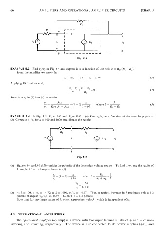
EXAMPLE 5.3 Find v 2 =v s in Fig. 5-4 and express it as a function of the ratio b ¼ R 1 =ðR 1 þ R 2 Þ.
From the amplifier we know that
or v 1 ¼ v 2 =k ð3Þ
v 2 ¼ kv 1
Applying KCL at node A,
v 1 v s v 1 v 2
þ ¼ 0 ð4Þ
R 1 R 2
Substitute v 1 in (3) into (4) to obtain
R 2 k k
v 2 R 1
¼ ¼ð1 bÞ where b ¼ ð5Þ
v s R 2 þ R 1 R 1 k 1 bk R 1 þ R 2
EXAMPLE 5.4 In Fig. 5-5, R 1 ¼ 1k
and R 2 ¼ 5k
. (a) Find v 2 =v s as a function of the open-loop gain k.
(b) Compute v 2 =v s for k ¼ 100 and 1000 and discuss the results.
Fig. 5-5
(a) Figures 5-4 and 5-5 differ only in the polarity of the dependent voltage source. To find v 2 =v s , use the results of
Example 5.3 and change k to k in (5).
k 1
v 2 R 1
¼ð1 bÞ where b ¼ ¼
v s 1 þ bk R 1 þ R 2 6
v 2 5k
¼
v s 6 þ k
(b)At k ¼ 100, v 2 =v s ¼ 4:72; at k ¼ 1000, v 2 =v s ¼ 4:97. Thus, a tenfold increase in k produces only a 5.3
percent change in v 2 =v s ; i.e., ð4:97 4:72Þ=4:72 ¼ 5:3 percent.
Note that for very large values of k, v 2 =v s approaches R 2 =R 1 which is independent of k.
5.3 OPERATIONAL AMPLIFIERS
The operational amplifier (op amp) is a device with two input terminals, labeled þ and or non-
inverting and inverting, respectively. The device is also connected to dc power supplies (þV cc and