
Page 81 - Schaum's Outline of Theory and Problems of Electric Circuits
P. 81
AMPLIFIERS AND OPERATIONAL AMPLIFIER CIRCUITS
70
Substituting v d in (7) into (6), the ratio v 2 =v 1 is found to be [CHAP. 5
5
v 2
¼ ¼ 5
v 1 1 þ 10 5 þ 5 10 5 þ 0:1 10 5
5.4 ANALYSIS OF CIRCUITS CONTAINING IDEAL OP AMPS
In an ideal op amp, R i and A are infinite and R o is zero. Therefore, the ideal op amp draws zero
current at its inverting and noninverting inputs, and if it is not saturated these inputs are at the same
voltage. Throughout this chapter we assume op amps are ideal and operate in the linear range unless
specified otherwise.
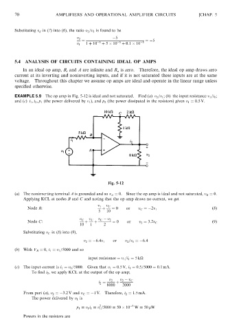
EXAMPLE 5.9 The op amp in Fig. 5-12 is ideal and not saturated. Find (a) v 2 =v 1 ;(b) the input resistance v 1 =i 1 ;
and (c) i 1 ; i 2 ; p 1 (the power delivered by v 1 ), and p 2 (the power dissipated in the resistors) given v 1 ¼ 0:5V.
Fig. 5-12
(a) The noninverting terminal A is grounded and so v A ¼ 0. Since the op amp is ideal and not saturated, v B ¼ 0.
Applying KCL at nodes B and C and noting that the op amp draws no current, we get
v 1 v C
Node B: þ ¼ 0 or v C ¼ 2v 1 (8)
5 10
v C v C v C v 2
Node C: þ þ ¼ 0 or v 2 ¼ 3:2v C (9)
10 1 2
Substituting v C in (8) into (9),
v 2 ¼ 6:4v 1 or v 2 =v 1 ¼ 6:4
(b) With V B ¼ 0, i 1 ¼ v 1 =5000 and so
input resistance ¼ v 1 =i 1 ¼ 5k
(c) The input current is i 1 ¼ v 1 =5000. Given that v 1 ¼ 0:5V, i 1 ¼ 0:5=5000 ¼ 0:1 mA.
To find i 2 , we apply KCL at the output of the op amp;
v 2 v 2 v C
i 2 ¼ þ
8000 2000
From part (a), v 2 ¼ 3:2 V and v C ¼ 1 V. Therefore, i 2 ¼ 1:5 mA.
The power delivered by v 1 is
2
p 1 ¼ v 1 i 1 ¼ v 1 =5000 ¼ 50 10 6 W ¼ 50 mW
Powers in the resistors are