Page 82 - Schaum's Outline of Theory and Problems of Electric Circuits
P. 82

CHAP. 5]
                                                2
                                         p 1k
 ¼ v C =1000 ¼ 0:001 W ¼ 1000 mW
                        1k
:     AMPLIFIERS AND OPERATIONAL AMPLIFIER CIRCUITS                        71
                                                      2
                        2k
:             p 2k
 ¼ðv 2   v C Þ =2000 ¼ 0:00242 W ¼ 2420 mW
                                                2
                        5k
:             p 5k
 ¼ v 1 =5000 ¼ 0:00005 W ¼ 50 mW
                                                2
                        8k
:             p 8k
 ¼ v 2 =8000 ¼ 0:00128 W ¼ 1280 mW
                                                2
                       10 k
:            p 10 k
 ¼ v C =10 000 ¼ 0:0001 W ¼ 100 mW
                       The total power dissipated in the resistors is
                          p 2 ¼ p 1k
 þ p 2k
 þ p 5k
 þ p 8k
 þ p 10 k
 ¼ 1000 þ 2420 þ 50 þ 1280 þ 100 ¼ 4850 mW


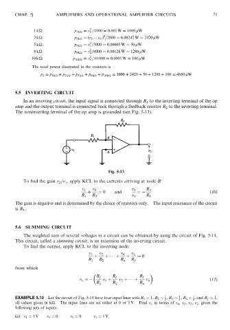
               5.5  INVERTING CIRCUIT
                   In an inverting circuit, the input signal is connected through R 1 to the inverting terminal of the op
               amp and the output terminal is connected back through a feedback resistor R 2 to the inverting terminal.
               The noninverting terminal of the op amp is grounded (see Fig. 5-13).


                                                        Fig. 5-13
                   To find the gain v 2 =v 1 , apply KCL to the currents arriving at node B:

                                             v 1  v 2             v 2    R 2
                                               þ    ¼ 0    and       ¼                              ð10Þ
                                            R 1  R 2              v 1    R 1
               The gain is negative and is determined by the choice of resistors only.  The input resistance of the circuit
               is R 1 .


               5.6  SUMMING CIRCUIT
                   The weighted sum of several voltages in a circuit can be obtained by using the circuit of Fig. 5-14.
               This circuit, called a summing circuit, is an extension of the inverting circuit.
                   To find the output, apply KCL to the inverting node:
                                                v 1  v 2      v n  v o
                                                  þ    þ     þ  þ    ¼ 0
                                               R 1  R 2      R n  R f
               from which

                                                   R f    R f         R f
                                            v o ¼     v 1 þ  v 2 þ     þ  v n                       ð11Þ
                                                   R 1    R 2         R n

                                                                                       1
                                                                                 1
                                                                                             1
               EXAMPLE 5.10 Let the circuit of Fig. 5-14 have four input lines with R 1 ¼ 1; R 2 ¼ ; R 3 ¼ ; R 4 ¼ , and R f ¼ 1,
                                                                                 2     4     8
               all values given in k
.  The input lines are set either at 0 or 1 V.  Find v o in terms of v 4 , v 3 , v 2 , v 1 , given the
               following sets of inputs:
               (a) v 4 ¼ 1V  v 3 ¼ 0   v 2 ¼ 0    v 1 ¼ 1V
   77   78   79   80   81   82   83   84   85   86   87