
Page 83 - Schaum's Outline of Theory and Problems of Electric Circuits
P. 83
AMPLIFIERS AND OPERATIONAL AMPLIFIER CIRCUITS
72
Fig. 5-14 [CHAP. 5
(b) v 4 ¼ 1V v 3 ¼ 1V v 2 ¼ 1V v 1 ¼ 0
From (11)
v o ¼ ð8v 4 þ 4v 3 þ 2v 2 þ v 1 Þ
Substituting for v 1 to v 4 we obtain
ðaÞ v o ¼ 9V
ðbÞ v o ¼ 14 V
The set fv 4 ; v 3 ; v 2 ; v 1 g forms a binary sequence containing four bits at high (1 V) or low (0 V) values. Input sets
given in (a) and (b) correspond to the binary numbers ð1001Þ ¼ð9Þ 10 and ð1110Þ ¼ð14Þ , respectively. With the
10
2
2
inputs at 0 V (low) or 1 V (high), the circuit converts the binary number represented by the input set fv 4 ; v 3 ; v 2 ; v 1 g to
a negative voltage which, when measured in V, is equal to the base 10 representation of the input set. The circuit is
a digital-to-analog converter.
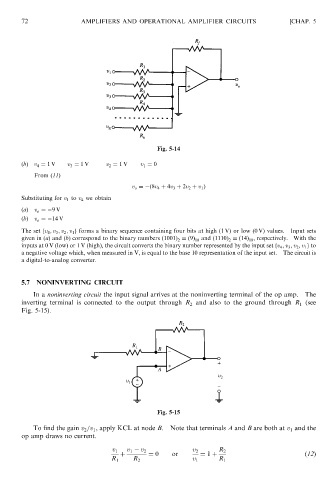
5.7 NONINVERTING CIRCUIT
In a noninverting circuit the input signal arrives at the noninverting terminal of the op amp. The
inverting terminal is connected to the output through R 2 and also to the ground through R 1 (see
Fig. 5-15).
Fig. 5-15
To find the gain v 2 =v 1 , apply KCL at node B. Note that terminals A and B are both at v 1 and the
op amp draws no current.
v 1 v 1 v 2 v 2 R 2
þ ¼ 0 or ¼ 1 þ ð12Þ
R 1 R 2 v 1 R 1