Page 88 - Schaum's Outline of Theory and Problems of Electric Circuits
P. 88

AMPLIFIERS AND OPERATIONAL AMPLIFIER CIRCUITS
               CHAP. 5]
                                                                                                      77
                                                                5
                                            v 2 ¼ ð9=5Þv 1 ¼ ð9=5Þ  v s  ¼ 1:5v s
                                                                6
                                            v o ¼ ð6=1:2Þv 2 ¼ 5ð 1:5v s Þ¼ 7:5v s
                                                     v s
                                             i s ¼ i 1 ¼  ðAÞ¼ 0:166v s ðmAÞ
                                                    6000
                                            i f ¼ 0
               (b) R f ¼ 40 k
. From the inverting op amps we get v o ¼ 5v 2 and v 2 ¼ ð9=5Þv 1 so that v o ¼ 9v 1 . Apply KCL
                   to the currents leaving node B.
                                                    v 1   v s  v 1  v 1   v o
                                                         þ   þ       ¼ 0                             ð19Þ
                                                      1    5     40
                   Substitute v o ¼ 9v 1 in (19) and solve for v 1 to get

                                                v 1 ¼ v s
                                                v 2 ¼ ð9=5Þv 1 ¼ 1:8v s
                                                v o ¼ ð6=1:2Þv 2 ¼ 5ð 1:8v s Þ¼ 9v s
                                                    v s   v 1
                                                i s ¼    ¼ 0
                                                    1000
                   Apply KCL at node B.
                                                     v 1      v s
                                             i f ¼ i 1 ¼  ðAÞ¼   ðAÞ¼ 0:2v s ðmAÞ
                                                    5000     5000
                   The current i 1 in the 5-k
 input resistor of the first op amp is provided by the output of the second op amp
                   through the 40-k
 feedback resistor. The current i s drawn from v s is, therefore, zero. The input resistance of
                   the circuit is infinite.


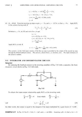
               5.11  INTEGRATOR AND DIFFERENTIATOR CIRCUITS
               Integrator
                   By replacing the feedback resistor in the inverting amplifier of Fig. 5-13 with a capacitor, the basic
               integrator circuit shown in Fig. 5-23 will result.


                                                        Fig. 5-23

                   To obtain the input-output relationship apply KCL at the inverting node:
                                                                             1
                                      v 1   dv 2                     dv 2
                                        þ C    ¼ 0     from which       ¼       v 1
                                      R      dt                      dt     RC
                                                             ð
                                                          1   t
               and                                 v ¼           v dt                               (20)
                                                    2
                                                                 1
                                                         RC    1
               In other words, the output is equal to the integral of the input multiplied by a gain factor of  1=RC.

               EXAMPLE 5.17   In Fig. 5-23 let R ¼ 1k
, C ¼ 1 mF, and v 1 ¼ sin 2000t. Assuming v 2 ð0Þ¼ 0, find v 2 for t > 0.
   83   84   85   86   87   88   89   90   91   92   93