
Page 89 - Schaum's Outline of Theory and Problems of Electric Circuits
P. 89
AMPLIFIERS AND OPERATIONAL AMPLIFIER CIRCUITS
78
ð t [CHAP. 5
1
v 2 ¼ 3 6 sin 2000tdt ¼ 0:5ðcos 2000t 1Þ
10 10 0
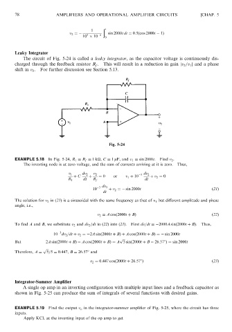
Leaky Integrator
The circuit of Fig. 5-24 is called a leaky integrator, as the capacitor voltage is continuously dis-
charged through the feedback resistor R f . This will result in a reduction in gain jv 2 =v 1 j and a phase
shift in v 2 . For further discussion see Section 5.13.
Fig. 5-24
EXAMPLE 5.18 In Fig. 5-24, R 1 ¼ R f ¼ 1k
, C ¼ 1 mF, and v 1 ¼ sin 2000t. Find v 2 .
The inverting node is at zero voltage, and the sum of currents arriving at it is zero. Thus,
v 1 dv 2 v 2 3 dv 2
þ C þ ¼ 0 or v 1 þ 10 þ v 2 ¼ 0
R 1 dt R f dt
10 3 dv 2 þ v 2 ¼ sin 2000t ð21Þ
dt
The solution for v 2 in (21) is a sinusoidal with the same frequency as that of v 1 but different amplitude and phase
angle, i.e.,
v 2 ¼ A cosð2000t þ BÞ ð22Þ
To find A and B, we substitute v 2 and dv 2 =dt in (22) into (21). First dv=dt ¼ 2000A sinð2000t þ BÞ. Thus,
3
10 dv 2 =dt þ v 2 ¼ 2A sinð2000t þ BÞþ A cosð2000t þ BÞ¼ sin 2000t
p ffiffiffi
But 2A sinð2000t þ BÞ A cosð2000t þ BÞ¼ A 5 sinð2000t þ B 26:578Þ¼ sin 2000t
p ffiffiffi
Therefore, A ¼ 5=5 ¼ 0:447, B ¼ 26:578 and
v 2 ¼ 0:447 cosð2000t þ 26:578Þ ð23Þ
Integrator-Summer Amplifier
A single op amp in an inverting configuration with multiple input lines and a feedback capacitor as
shown in Fig. 5-25 can produce the sum of integrals of several functions with desired gains.
EXAMPLE 5.19 Find the output v o in the integrator-summer amplifier of Fig. 5-25, where the circuit has three
inputs.
Apply KCL at the inverting input of the op amp to get