Page 90 - Schaum's Outline of Theory and Problems of Electric Circuits
P. 90

AMPLIFIERS AND OPERATIONAL AMPLIFIER CIRCUITS
               CHAP. 5]


                                                        Fig. 5-25                                     79


                                                  v 1  v 2  v 3  dv o
                                                    þ   þ   þ C    ¼ 0
                                                 R 1  R 2  R 3  dt
                                                   ð t
                                                         v 1  v 2   v 3
                                              v o ¼         þ    þ      dt                           ð24Þ
                                                     1 R 1 C  R 2 C  R 3 C
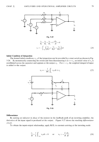
               Initial Condition of Integration
                   The desired initial condition, v o , of the integration can be provided by a reset switch as shown in Fig.
               5-26.  By momentarily connecting the switch and then disconnecting it at t ¼ t o , an initial value of v o is
               established across the capacitor and appears at the output v 2 . For t > t o , the weighted integral of input
               is added to the output.
                                                           ð t
                                                         1
                                                 v 2 ¼        v 1 dt þ v o                          ð25Þ
                                                        RC
                                                            t o


                                                        Fig. 5-26


               Differentiator
                   By putting an inductor in place of the resistor in the feedback path of an inverting amplifier, the
               derivative of the input signal is produced at the output.  Figure 5-27 shows the resulting differentiator
               circuit.
                   To obtain the input-output relationship, apply KCL to currents arriving at the inverting node:


                                              ð t
                                             1
                                        v 1                               L dv 1
                                          þ        v 2 dt ¼ 0  or   v 2 ¼                           ð26Þ
                                        R   L   1                         R dt
   85   86   87   88   89   90   91   92   93   94   95