
Page 248 - Semiconductor Manufacturing Handbook
P. 248
Geng(SMH)_CH17.qxd 04/04/2005 19:57 Page 17.3
CHEMICAL MECHANICAL POLISHING
CHEMICAL MECHANICAL POLISHING 17.3
17.2 MOST COMMON CMP PROCESSES
There are many polishing systems in CMP. For illustrative purposes, we will discuss two different
but very common polishing systems. These systems are silicon dioxide (Oxide) CMP and tungsten
CMP. Additional common CMP process will also be briefly discussed.
17.2.1 Oxide/Poly Si CMP
The most basic and common CMP process is called ILD CMP. This process is relatively mechanical
in nature and follows Preston’s law quite well. ILD CMP processes typically use silica-based abra-
sives in KOH-based solution to polish silicon dioxide films. During ILD CMP, KOH chemically soft-
ens the silica film on the wafer in the presence of a mechanically applied pressure. Silica abrasives
in the polishing solution, carried by the polyurethane pad (Rodel IC1000), abrade away the softened
film layer on the wafer surface. This process is quite elegant since during polishing the fine abrasives
particles also dissolve by the same softening mechanism, therefore reducing scratching defects.
Planarization during oxide ILD CMP is fairly easy to explain. Since mechanical forces are
required to soften the silica films in alkaline chemistries, die level features that protrude from the
wafer surface are preferentially removed by high localized pressures. Using a more rigid polishing
pad or pad stack further enhances this dimensional selectivity and can improve the planarization effi-
ciency. As features flatten, the local surface area being polished actually increases due to the erosion
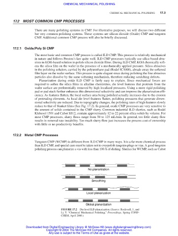
of protruding elements. As local die level features flatten, polishing pressures that generate dimen-
sional selectivity are reduced. Due to topography changes, the polishing rates of high features slowly
reduce to that of blanket films (See Fig. 17.2). In general, oxide CMP processes are very sensitive to
the amount of solids contained in the CMP slurry. Common industrial ILD slurries, such as Rodel
Klebesol 1501 and Cabot SS12, contain approximately 12 to 22 percent silica solids by volume. For
most CMP processes, slurry flows range from 50 to 125 mL/min. In general, too little slurry flow
results in removal rate instability. Too much slurry flow just increases the process cost of ownership
with little or no productivity benefits.
17.2.2 Metal CMP Processes
Tungsten CMP (WCMP) is different from ILD CMP in many ways. It is a far more chemical process
than ILD CMP, and special care must be taken not to overpolish tungsten plugs or vias. A good tungsten
polishing process can planarize a via with less than 100 Å of dishing. Slurries for WCMP, such as Cabot
No planarization
Smoothing
Local planarization
Global planarization
FIGURE 17.2 Die level ILD planarization.(Source: Rockwell, J., and
Li, Y. “Chemical Mechanical Polishing,” Proceedings, Spring CONF-
CHEM, April 2000.)
Downloaded from Digital Engineering Library @ McGraw-Hill (www.digitalengineeringlibrary.com)
Copyright © 2004 The McGraw-Hill Companies. All rights reserved.
Any use is subject to the Terms of Use as given at the website.