
Page 171 - Sensing, Intelligence, Motion : How Robots and Humans Move in an Unstructured World
P. 171
146 ACCOUNTING FOR BODY DYNAMICS: THE JOGGER’S PROBLEM
t
n
p
q V i
Θ i
C i
y
S x
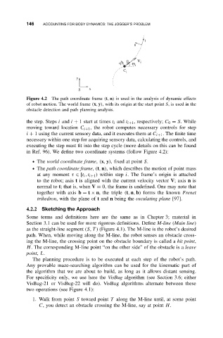
Figure 4.2 The path coordinate frame (t, n) is used in the analysis of dynamic effects
of robot motion. The world frame (x, y), with its origin at the start point S,is usedin the
obstacle detection and path planning analysis.
the step. Steps i and i + 1 start at times t i and t i+1 , respectively; C 0 = S. While
moving toward location C i+1 , the robot computes necessary controls for step
i + 1 using the current sensory data, and it executes them at C i+1 . The finite time
necessary within one step for acquiring sensory data, calculating the controls, and
executing the step must fit into the step cycle (more details on this can be found
in Ref. 96). We define two coordinate systems (follow Figure 4.2):
• The world coordinate frame, (x, y), fixed at point S.
• The path coordinate frame, (t, n), which describes the motion of point mass
at any moment τ ∈ [t i ,t i+1 ) within step i. The frame’s origin is attached
to the robot; axis t is aligned with the current velocity vector V;axis n is
normal to t;that is, when V = 0, the frame is undefined. One may note that
together with axis b = t × n, the triple (t, n, b) forms the known Frenet
trihedron, with the plane of t and n being the osculating plane [97].
4.2.2 Sketching the Approach
Some terms and definitions here are the same as in Chapter 3; material in
Section 3.1 can be used for more rigorous definitions. Define M-line (Main line)
as the straight-line segment (S, T ) (Figure 4.1). The M-line is the robot’s desired
path. When, while moving along the M-line, the robot senses an obstacle cross-
ing the M-line, the crossing point on the obstacle boundary is called a hit point,
H. The corresponding M-line point “on the other side” of the obstacle is a leave
point, L.
The planning procedure is to be executed at each step of the robot’s path.
Any provable maze-searching algorithm can be used for the kinematic part of
the algorithm that we are about to build, as long as it allows distant sensing.
For specificity only, we use here the VisBug algorithm (see Section 3.6; either
VisBug-21 or VisBug-22 will do). VisBug algorithms alternate between these
two operations (see Figure 4.1):
1. Walk from point S toward point T along the M-line until, at some point
C, you detect an obstacle crossing the M-line, say at point H.