
Page 174 - Sensing, Intelligence, Motion : How Robots and Humans Move in an Unstructured World
P. 174
MAXIMUM TURN STRATEGY 149
V 1 V 2 x
C 1 C 2 B 1
O 1
r u
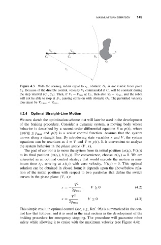
Figure 4.3 With the sensing radius equal to r v , obstacle O 1 is not visible from point
C 1 . Because of the discrete control, velocity V 1 commanded at C 1 will be constant during
the step interval (C 1 ,C 2 ). Then, if V 1 = V max at C 1 ,thenalso V 2 = V max , and the robot
will not be able to stop at B 1 , causing collision with obstacle O 1 . The permitted velocity
thus must be V p max <V max .
4.2.4 Optimal Straight-Line Motion
We now sketch the optimization scheme that will later be used in the development
of the braking procedure. Consider a dynamic system, a moving body whose
behavior is described by a second-order differential equation ¨x = p(t),where
p(t) ≤ p max and p(t) is a scalar control function. Assume that the system
moves along a straight line. By introducing state variables x and V , the system
equations can be rewritten as ˙x = V and V = p(t). It is convenient to analyze
˙
the system behavior in the phase space (V , x).
The goal of control is to move the system from its initial position (x(t 0 ), V (t 0 ))
to its final position (x(t f ), V (t f )). For convenience, choose x(t f ) = 0. We are
interested in an optimal control strategy that would execute the motion in min-
imum time t f , arriving at x(t f ) with zero velocity, V(t f ) = 0. This optimal
solution can be obtained in closed form; it depends upon the above/below rela-
tion of the initial position with respect to two parabolas that define the switch
curves in the phase plane (V , x):
V 2
x =− , V ≥ 0 (4.2)
2p max
V 2
x = , V ≤ 0 (4.3)
2p max
This simple result in optimal control (see, e.g., Ref. 98) is summarized in the con-
trol law that follows, and it is used in the next section in the development of the
braking procedure for emergency stopping. The procedure will guarantee robot
safety while allowing it to cruise with the maximum velocity (see Figure 4.4):