
Page 175 - Sensing, Intelligence, Motion : How Robots and Humans Move in an Unstructured World
P. 175
150 ACCOUNTING FOR BODY DYNAMICS: THE JOGGER’S PROBLEM
Start
(v , x ) position
s
s
, x )
(v o o
Point of
switching
v
Start
position
Final , x )
(v s s
position
(v , x ) Point of
o
o
switching
Switch
curve
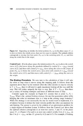
Figure 4.4 Depending on whether the initial position (V 0 ,x 0 ) in the phase space (V, x)
is above or below the switch curves, there are two cases to consider. The optimal solution
corresponds to moving first from point (V 0 ,x 0 ) to the switching point (V s ,x s ) and then
along the switch line to the origin.
Control Law: If in the phase space the initial position (V 0 ,x 0 ) is above the switch
curve (4.2), first move along the parabola defined by control ˆp =−p max toward
curve (4.2), and then with control ˆp = p max move along the curve to the origin. If
point (V 0 ,x 0 ) is below the switch curve, move first with control ˆp = p max toward
the switch curve (4.3), and then move with control ˆp =−p max along the curve to
the origin.
The Braking Procedure. We now turn to the calculation of time it will take
the robot to stop when it moves along the stopping path. It follows from the
argument above that if at the moment when the robot decides to stop its velocity
is V = V p max , then it will need to apply maximum braking all the way until the
stop. This will define uniquely the time to stop. But, if V< V p max , then there
are a variety of braking strategies and hence of different times to stop.
Consider again the example in Figure 4.3; assume that at point C 2 ,V 2 <
V p max . What is the optimal braking strategy, the one that guarantees safety while
bringing the robot in minimum time to a stop at the sensing range boundary?
While this strategy is not necessarily the one we would want to implement, it is
of interest because it defines the limit velocity profile the robot can maintain for
safe braking. The answer is given by the solution of an optimization problem for
a single-degree-of-freedom system. It follows from the Control Law above that
the optimal solution corresponds to at most two curves, I and II, in the phase
space (V, x) (Figure 4.5a) and to at most one control switch, from ˆp = p max on
line I to ˆp =−p max on line II, given by (4.2) and (4.3). For example, if braking