
Page 267 - Sensing, Intelligence, Motion : How Robots and Humans Move in an Unstructured World
P. 267
242 MOTION PLANNING FOR TWO-DIMENSIONAL ARM MANIPULATORS
M 1
A
4
5 0 1 3
1
6
T 10 A S
7
2,3,5,6 5
9
2
11 S,1,4,9 2
7
6 3
S
7,8,10,11 T
B 8 1 M 1 4 11
9 8 10
7
B
0
q = 90°
q = 0 2
2
(a) (b)
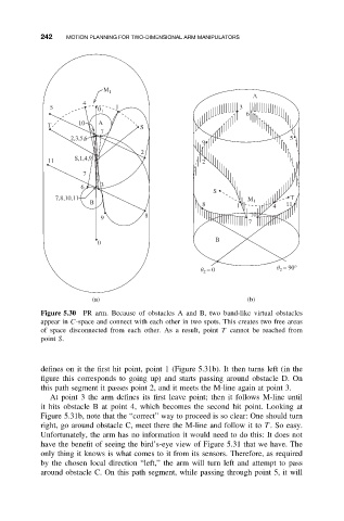
Figure 5.30 PR arm. Because of obstacles A and B, two band-like virtual obstacles
appear in C-space and connect with each other in two spots. This creates two free areas
of space disconnected from each other. As a result, point T cannot be reached from
point S.
defines on it the first hit point, point 1 (Figure 5.31b). It then turns left (in the
figure this corresponds to going up) and starts passing around obstacle D. On
this path segment it passes point 2, and it meets the M-line again at point 3.
At point 3 the arm defines its first leave point; then it follows M-line until
it hits obstacle B at point 4, which becomes the second hit point. Looking at
Figure 5.31b, note that the “correct” way to proceed is so clear: One should turn
right, go around obstacle C, meet there the M-line and follow it to T .Soeasy.
Unfortunately, the arm has no information it would need to do this: It does not
have the benefit of seeing the bird’s-eye view of Figure 5.31 that we have. The
only thing it knows is what comes to it from its sensors. Therefore, as required
by the chosen local direction “left,” the arm will turn left and attempt to pass
around obstacle C. On this path segment, while passing through point 5, it will