
Page 53 - Sensing, Intelligence, Motion : How Robots and Humans Move in an Unstructured World
P. 53
28 A QUICK SKETCH OF MAJOR ISSUES IN ROBOTICS
Of these and other issues mentioned above, the last one, motion planning and
collision avoidance, is the central problem in robotics—first, because it appears
in just about any robotic task and application, and, second, because it appears
to be the most “robotic” issue in robotics. Indeed, the other areas above have
been developed in, and are of importance to, other engineering fields, not only
to robotics, whereas the subject of motion planning and collision avoidance is
unique to robotics. For example, kinematics, statics, and dynamics are central
to the design of an immense variety of machines (of which robots are only a
small part); feedback control is the central issue in control theory and control
engineering; and so on.
Readers interested in deeper understanding of those and other issues are
referred to other sources; some such will be cited in the sequel.
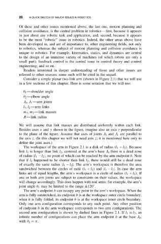
Consider a simple planar two-link arm (shown in Figure 2.1) that we will use
in a few sections of this chapter. Here is some notation that we will use:
θ 1 —shoulder angle
θ 2 —elbow angle
J 0 ,J 1 —arm joints
l 1 ,l 2 —arm links
m 1 ,m 2 —link masses
R—link radius
We will assume that link masses are distributed uniformly within each link.
Besides axes x and y shown in the figure, imagine also an axis z perpendicular
to the plane of the figure. Assume that axes of joints J 0 and J 1 are parallel to
the axis z. (In this chapter we will not need axis z; it is mentioned here only to
define the joint axes.)
The workspace of the arm in Figure 2.1 is a disk of radius (l 1 + l 2 ). Because
link l 1 is longer than link l 2 , centered at the arm’s base J 0 there is a dead zone
of radius |l 1 − l 2 |, no point of which can be reached by the arm endpoint b.Note
that if l 1 happened to be shorter than link l 2 , there would still be a dead zone
of exactly the same radius |l 1 − l 2 |. The arm’s workspace is therefore the area
sandwiched between the circles of radii (l 1 + l 2 ) and |l 1 − l 2 |. In case the arm
links are of equal lengths, the arm’s workspace is a circle of radius (l 1 + l 2 ).If
one or both arm joints are subject to constraints on their values, the workspace
will change accordingly. This does happen with real arms; for example, the arm’s
joint angle θ 1 may be limited to the range ±120 .
◦
The arm’s endpoint b can occupy any point in the arm’s workspace. When the
arm is fully outstretched, its endpoint b is at the workspace outer circle boundary;
when it is fully folded, its endpoint b is at the workspace inner circle boundary.
Only one arm configuration corresponds to any such point. Any other position
of endpoint b in the arm workspace corresponds to two arm configurations. The
second arm configuration is shown by dashed lines in Figure 2.1. If l 1 = l 2 ,an
infinite number of configurations can place the arm endpoint b at the base J 0 ,
with θ 2 = π.