
Page 54 - Sensing, Intelligence, Motion : How Robots and Humans Move in an Unstructured World
P. 54
KINEMATICS 29
R
b
y
Θ 2
l 2
a
J 1
l 1
Θ 1
x
J o
l 1 – l 2
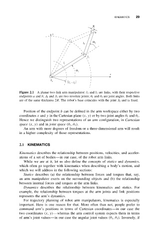
Figure 2.1 A planar two-link arm manipulator: l 1 and l 2 are links, with their respective
endpoints a and b; J 0 and J 1 are two revolute joints; θ 1 and θ 2 are joint angles. Both links
are of the same thickness 2R. The robot’s base coincides with the joint J 0 and is fixed.
Position of the endpoint b can be defined in the arm workspace either by two
coordinates x and y in the Cartesian plane (x, y) or by two joint angles θ 1 and θ 1 .
Hence we distinguish two representations of an arm configuration, in Cartesian
space (x, y) and in joint space (θ 1 ,θ 1 ).
An arm with more degrees of freedom or a three-dimensional arm will result
in a higher complexity of those representations.
2.1 KINEMATICS
Kinematics describes the relationship between positions, velocities, and acceler-
ations of a set of bodies—in our case, of the robot arm links.
While we are at it, let us also define the concepts of statics and dynamics,
which often go together with kinematics when describing a body’s motion, and
which we will address in the following sections:
Statics describes (a) the relationship between forces and torques that, say,
an arm manipulator exerts on the surrounding objects and (b) the relationship
between internal forces and torques at the arm links.
Dynamics describes the relationship between kinematics and statics. For
example, the relationship between torques at the arm joints and link positions
represents the arm’s dynamics.
For trajectory planning of robot arm manipulators, kinematics is especially
important. Here is one reason for that. More often than not, people prefer to
command arm’s positions in terms of Cartesian coordinates—in our case the
two coordinates (x, y)—whereas the arm control system expects them in terms
of arm’s joint values—in our case the angular joint values (θ 1 ,θ 1 ). Inversely, if