
Page 389 - Sensors and Control Systems in Manufacturing
P. 389
0.5 Industrial Sensors and Contr ol 343
Drift/nm 0
–0.5
–1
0 0.5 1 1.5 2 2.5 3 3.5
Time/h
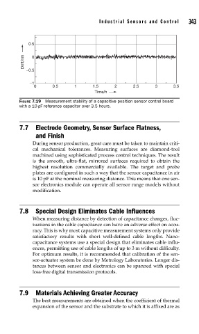
FIGURE 7.19 Measurement stability of a capacitive position sensor control board
with a 10-pF reference capacitor over 3.5 hours.
7.7 Electrode Geometry, Sensor Surface Flatness,
and Finish
During sensor production, great care must be taken to maintain criti-
cal mechanical tolerances. Measuring surfaces are diamond-tool
machined using sophisticated process control techniques. The result
is the smooth, ultra-flat, mirrored surfaces required to obtain the
highest resolution commercially available. The target and probe
plates are configured in such a way that the sensor capacitance in air
is 10 pF at the nominal measuring distance. This means that one sen-
sor electronics module can operate all sensor range models without
modification.
7.8 Special Design Eliminates Cable Influences
When measuring distance by detection of capacitance changes, fluc-
tuations in the cable capacitance can have an adverse effect on accu-
racy. This is why most capacitive measurement systems only provide
satisfactory results with short well-defined cable lengths. Nano-
capacitance systems use a special design that eliminates cable influ-
ences, permitting use of cable lengths of up to 3 m without difficulty.
For optimum results, it is recommended that calibration of the sen-
sor-actuator system be done by Metrology Laboratories. Longer dis-
tances between sensor and electronics can be spanned with special
loss-free digital transmission protocols.
7.9 Materials Achieving Greater Accuracy
The best measurements are obtained when the coefficient of thermal
expansion of the sensor and the substrate to which it is affixed are as