
Page 394 - Sensors and Control Systems in Manufacturing
P. 394
348
Se v e n
Cha p te r
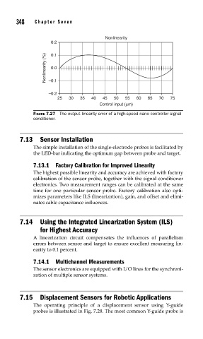
Nonlinearity
0.2
Nonlinearity (%) –0.1
0.1
0.0
–0.2
25 30 35 40 45 50 55 60 65 70 75
Control input (μm)
FIGURE 7.27 The output linearity error of a high-speed nano controller signal
conditioner.
7.13 Sensor Installation
The simple installation of the single-electrode probes is facilitated by
the LED-bar indicating the optimum gap between probe and target.
7.13.1 Factory Calibration for Improved Linearity
The highest possible linearity and accuracy are achieved with factory
calibration of the sensor probe, together with the signal conditioner
electronics. Two measurement ranges can be calibrated at the same
time for one particular sensor probe. Factory calibration also opti-
mizes parameters like ILS (linearization), gain, and offset and elimi-
nates cable capacitance influences.
7.14 Using the Integrated Linearization System (ILS)
for Highest Accuracy
A linearization circuit compensates the influences of parallelism
errors between sensor and target to ensure excellent measuring lin-
earity to 0.1 percent.
7.14.1 Multichannel Measurements
The sensor electronics are equipped with I/O lines for the synchroni-
zation of multiple sensor systems.
7.15 Displacement Sensors for Robotic Applications
The operating principle of a displacement sensor using Y-guide
probes is illustrated in Fig. 7.28. The most common Y-guide probe is