
Page 397 - Sensors and Control Systems in Manufacturing
P. 397
Industrial Sensors and Contr ol
Optoelectronic 351
instrument
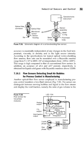
Optical fiber
connector Optical fiber Sensor
assembly
Microbend Metal
sensor C-ring
Sensor
Bar housing Metal Flowmeter
C-ring body
FIGURE 7.31 Schematic diagram of a vortex-shedding fl ow sensor.
accuracy is essentially independent of any changes in the fluid tem-
perature, viscosity, or density, and in the light source intensity.
According to the specifications for typical optical vortex-shedding
flow sensors, flow rate can be measured over a Reynolds number
range from 5 × 10 to 6000 × 10 at temperatures from –100 to +600°C.
3
3
This range is high compared to that of conventional flow meters. In
addition, an accuracy of ±0.4 and ±0.7 percent, respectively, is
obtained for liquids and gases with Reynolds numbers above 10,000.
7.16.1 Flow Sensors Detecting Small Air Bubbles
for Process Control in Manufacturing
Another optical-fiber flow sensor employed in manufacturing pro-
cess control monitors a two-fluid mixture (Fig. 7.32). The sensor can
distinguish between moving bubbles and liquid in the flow stream
and display the void fraction, namely, the ratio of gas volume to the
FIGURE 7.32 LED PIN
Flow sensor for
two-phase
mixtures.
Analog
output Signal
processor
Vold-fraction
TTL display
output
48.5%
Void-fraction
output Integration
Optical
Liquid fiber
phase
Optical
Gas sensor
phase