
Page 396 - Sensors and Control Systems in Manufacturing
P. 396
350
Cha p te r
Se v e n
linearity within 5 percent, and a dynamic range of 100 μm displace-
ment. Y-guide probe displacement sensors are well-suited for robot-
ics applications as position sensors and for gauging and surface
assessment since they have high sensitivity to small distances.
One profound problem of this type of displacement sensor is the
measuring error arising from the variation in parasitic losses along the
optical transmission line. Recalibration is required if the optical path is
interrupted, which limits the range of possible applications. In order
to overcome this problem, a line-loss-independent displacement sensor
with an electrical subcarrier phase encoder has been implemented. In
this sensor, the light from an LED modulated at 160 MHz is coupled
into the fiber bundle and divided into two optical paths. One of the paths
is provided with a fixed retroreflector at its end. The light through the
other is reflected by the object. The two beams are returned to the two
photodiodes separately. Each signal, converted into an electric voltage,
is electrically heterodyned into an intermediate frequency at 455 kHz.
Then, the two signals are fed to a digital phase comparator, the out-
put of which is proportional to the path distance. The resolution of
the optical path difference is about 0.3 mm, but improvement of the
receiver electronics will provide a higher resolution.
7.16 Process Control Sensors Measuring and
Monitoring Liquid Flow
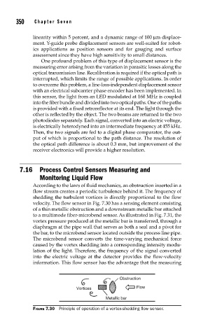
According to the laws of fluid mechanics, an obstruction inserted in a
flow stream creates a periodic turbulence behind it. The frequency of
shedding the turbulent vortices is directly proportional to the flow
velocity. The flow sensor in Fig. 7.30 has a sensing element consisting
of a thin metallic obstruction and a downstream metallic bar attached
to a multimode fiber-microbend sensor. As illustrated in Fig. 7.31, the
vortex pressure produced at the metallic bar is transferred, through a
diaphragm at the pipe wall that serves as both a seal and a pivot for
the bar, to the microbend sensor located outside the process line pipe.
The microbend sensor converts the time-varying mechanical force
caused by the vortex shedding into a corresponding intensity modu-
lation of the light. Therefore, the frequency of the signal converted
into the electric voltage at the detector provides the flow-velocity
information. This flow sensor has the advantage that the measuring
Obstruction
Vortices Flow
Metallic bar
FIGURE 7.30 Principle of operation of a vortex-shedding fl ow sensor.