
Page 395 - Sensors and Control Systems in Manufacturing
P. 395
Industrial Sensors and Contr ol
Transmitting fibers 349
Input light
Object
Output light
Receiving fibers Distance d
FIGURE 7.28 The principle of operation of a fi ber-optic mechanical sensor
using a Y-guide probe.
a bifurcated fiber bundle. The light emitted from one bundle is back-
reflected by the object to be measured and collected by another bun-
dle (receiving fibers). As a result, the returned light at the detector is
intensity-modulated to a degree dependent on the distance between
the end of the fiber bundle and the object. The sensitivity and the
dynamic range are determined by the geometrical arrangement of the
array of fiber bundles and by both the number and type of the fibers.
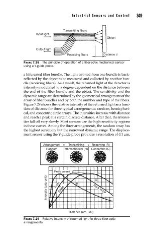
Figure 7.29 shows the relative intensity of the returned light as a func-
tion of distance for three typical arrangements: random, hemispheri-
cal, and concentric circle arrays. The intensities increase with distance
and reach a peak at a certain discrete distance. After that, the intensi-
ties fall off very slowly. Most sensors use the high-sensitivity regions
in these curves. Among the three arrangements, the random array has
the highest sensitivity but the narrowest dynamic range. The displace-
ment sensor using the Y-guide probe provides a resolution of 0.1 μm,
Arrangement o Transmitting o Receiving (R)
Random Hemspherical (H) Concentric (C)
Peak values
H
Intensity (arb. unit) Front Slope R Back slope
C
Distance (arb. unit)
FIGURE 7.29 Relative intensity of returned light for three fi ber-optic
arrangements