
Page 495 - Sensors and Control Systems in Manufacturing
P. 495
448
Cha p te r
Ni ne
The module contains an error voltage recognition facility, which
is activated when the input voltage exceeds specified tolerance limits.
A trigger circuit with signal delay (added in sequence) ensures that
momentary interference peaks are suppressed. Positive and negative
supply voltages (+V, –V) are provided at the input terminals for con-
nection of various sensors. Optocouplers separate internal and exter-
nal circuits so that interference is not able to penetrate the PLC via
conductive lines. The input module contains visual indicators (mainly
LEDs), which indicate whether a 1 or a 0 is present at the input.
The requirements at the output side are:
• Amplification of the output signals
• Protection against short circuiting
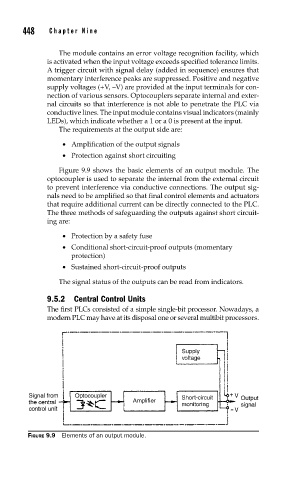
Figure 9.9 shows the basic elements of an output module. The
optocoupler is used to separate the internal from the external circuit
to prevent interference via conductive connections. The output sig-
nals need to be amplified so that final control elements and actuators
that require additional current can be directly connected to the PLC.
The three methods of safeguarding the outputs against short circuit-
ing are:
• Protection by a safety fuse
• Conditional short-circuit-proof outputs (momentary
protection)
• Sustained short-circuit-proof outputs
The signal status of the outputs can be read from indicators.
9.5.2 Central Control Units
The first PLCs consisted of a simple single-bit processor. Nowadays, a
modern PLC may have at its disposal one or several multibit processors.
FIGURE 9.9 Elements of an output module.