
Page 498 - Sensors and Control Systems in Manufacturing
P. 498
Communications
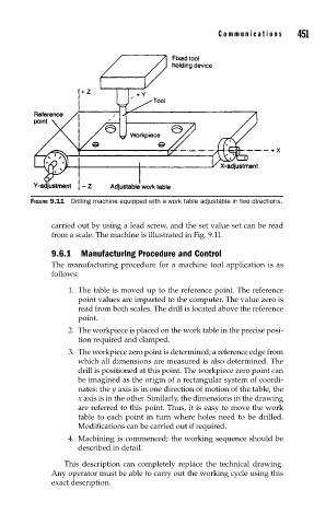
FIGURE 9.11 Drilling machine equipped with a work table adjustable in two directions. 451
carried out by using a lead screw, and the set value set can be read
from a scale. The machine is illustrated in Fig. 9.11.
9.6.1 Manufacturing Procedure and Control
The manufacturing procedure for a machine tool application is as
follows:
1. The table is moved up to the reference point. The reference
point values are imparted to the computer. The value zero is
read from both scales. The drill is located above the reference
point.
2. The workpiece is placed on the work table in the precise posi-
tion required and clamped.
3. The workpiece zero point is determined; a reference edge from
which all dimensions are measured is also determined. The
drill is positioned at this point. The workpiece zero point can
be imagined as the origin of a rectangular system of coordi-
nates: the y axis is in one direction of motion of the table, the
x axis is in the other. Similarly, the dimensions in the drawing
are referred to this point. Thus, it is easy to move the work
table to each point in turn where holes need to be drilled.
Modifications can be carried out if required.
4. Machining is commenced; the working sequence should be
described in detail.
This description can completely replace the technical drawing.
Any operator must be able to carry out the working cycle using this
exact description.