
Page 501 - Sensors and Control Systems in Manufacturing
P. 501
454
Ni ne
Cha p te r
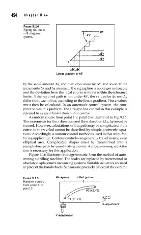
FIGURE 9.14
Zigzag course to
mill diagonal
groove.
by the same amount Δy, and then once more by Δx, and so on. If the
increments Δx and Δy are small, the zigzag line is no longer noticeable
and the deviation from the ideal course remains within the tolerance
limits. If the required path is not under 45°, the values for Δx and Δy
differ from each other, according to the linear gradient. These values
must then be calculated. In an automatic control system, the com-
puter solves this problem. The straight-line control in this example is
referred to as an extended straight-line control.
A random course from point 1 to point 2 is illustrated in Fig. 9.15.
The increments for the x direction and the y direction (Δx, Δy) must be
formed. However, calculations of this path may be complicated if the
curve to be traveled cannot be described by simple geometric equa-
tions. Accordingly, a contour control method is used in this manufac-
turing application. Contour controls can generally travel in arcs, even
elliptical arcs. Complicated shapes must be transformed into a
straight-line path by coordinating points. A programming worksta-
tion is necessary for this application.
Figure 9.16 illustrates in diagrammatic form the method of auto-
mating a drilling machine. The scales are replaced by incremental or
absolute displacement measuring systems. Suitable actuators are used
in place of the handwheels. Sensors are precisely placed at the extreme
FIGURE 9.15
Random course
from point 1 to
point 2.