
Page 500 - Sensors and Control Systems in Manufacturing
P. 500
Communications
In the example just described, the machining of the workpiece 453
takes place only at four different points; only one machining position
is approached. No rule exists as to which path should be taken to
reach this position. Thus, no changes have been made at the work-
piece when the drilling operation occurs, and the table is moved by a
zigzag course to the position for the second drilling operation. This is
referred to as a point-to-point control.
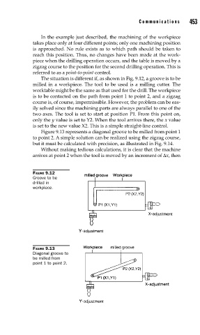
The situation is different if, as shown in Fig. 9.12, a groove is to be
milled in a workpiece. The tool to be used is a milling cutter. The
worktable might be the same as that used for the drill. The workpiece
is to be contacted on the path from point 1 to point 2, and a zigzag
course is, of course, impermissible. However, the problem can be eas-
ily solved since the machining parts are always parallel to one of the
two axes. The tool is set to start at position P1. From this point on,
only the y value is set to Y2. When the tool arrives there, the x value
is set to the new value X2. This is a simple straight-line control.
Figure 9.13 represents a diagonal groove to be milled from point 1
to point 2. A simple solution can be realized using the zigzag course,
but it must be calculated with precision, as illustrated in Fig. 9.14.
Without making tedious calculations, it is clear that the machine
arrives at point 2 when the tool is moved by an increment of Δx, then
FIGURE 9.12
Groove to be
drilled in
workpiece.
FIGURE 9.13
Diagonal groove to
be milled from
point 1 to point 2.