
Page 546 - Sensors and Control Systems in Manufacturing
P. 546
SpectRx NIR Technology
10.7.8 Johnson Noise (InSb Detectors) 499
Johnson noise, roughly defined, is the random variation of voltage
due to the thermal agitation of charge carriers in a resistor. Originally
described and measured by J. B. Johnson, a physicist at Bell Laborato-
ries who performed his experiments with a vacuum tube amplifier
and thermocouple, the effect was first explained theoretically by H.
Nyquist in 1928.
The Johnson noise (/A Hz ) of the feedback resistor of the first
stage of amplification is given by:
α
I Johnson =⋅ 4 kT (10.7)
R
f
where R = feedback resistor (Ω)
f
k = 1.38 × 10 J/K is the Boltzmann constant
–23
α = noise factor for imperfect resistors (no units), estimated
by the manufacturer to be 1.5
T = temperature of the resistor (K)
In the SpectRx design, Johnson noise never dominates the total
noise of the system. It increases the total system noise by less than 10
percent with the coldest object view temperature and by even less as
the object view temperature is increased.
10.7.8.1 In depth study of Johnson Noise (InSb Detectors)
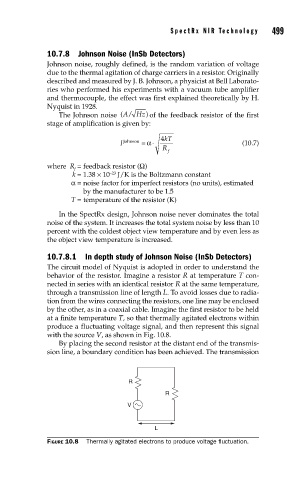
The circuit model of Nyquist is adopted in order to understand the
behavior of the resistor. Imagine a resistor R at temperature T con-
nected in series with an identical resistor R at the same temperature,
through a transmission line of length L. To avoid losses due to radia-
tion from the wires connecting the resistors, one line may be enclosed
by the other, as in a coaxial cable. Imagine the first resistor to be held
at a finite temperature T, so that thermally agitated electrons within
produce a fluctuating voltage signal, and then represent this signal
with the source V, as shown in Fig. 10.8.
By placing the second resistor at the distant end of the transmis-
sion line, a boundary condition has been achieved. The transmission
R
R
V
L
FIGURE 10.8 Thermally agitated electrons to produce voltage fl uctuation.