
Page 89 - Sensors and Control Systems in Manufacturing
P. 89
50
Cha p te r
T w o
2.2 Open- and Closed-Loop Control Systems
In an open-loop control system, the actual value in Fig. 2.4 may differ
from the reference value in the system. In a closed-loop system, the
actual value is constantly monitored against the reference value
described in Fig. 2.5.
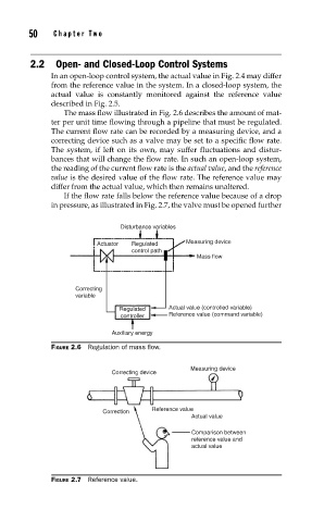
The mass flow illustrated in Fig. 2.6 describes the amount of mat-
ter per unit time flowing through a pipeline that must be regulated.
The current flow rate can be recorded by a measuring device, and a
correcting device such as a valve may be set to a specific flow rate.
The system, if left on its own, may suffer fluctuations and distur-
bances that will change the flow rate. In such an open-loop system,
the reading of the current flow rate is the actual value, and the reference
value is the desired value of the flow rate. The reference value may
differ from the actual value, which then remains unaltered.
If the flow rate falls below the reference value because of a drop
in pressure, as illustrated in Fig. 2.7, the valve must be opened further
Disturbance variables
Measuring device
Actuator Regulated
control path
Mass flow
Correcting
variable
Regulated Actual value (controlled variable)
controller Reference value (command variable)
Auxiliary energy
FIGURE 2.6 Regulation of mass fl ow.
Measuring device
Correcting device
Reference value
Correction
Actual value
Comparison between
reference value and
actual value
FIGURE 2.7 Reference value.