
Page 166 - Shale Shakers Drilling Fluid Systems
P. 166
SOLIDS CONTROL EQUIPMENT 149
particles exit at the vortex. The D 50 cut point of Stokes' Law
a solids separation device is defined as that par-
ticle size at which one-half of the weight of Stokes Law defines the relationship between
specific size particles go to the underflow and parameters that control the settling velocity of par-
one-half of the weight go to the overflow. For ex- ticles in viscous liquids, not only in settling pits
ample, a D 30 cut point references a particle size but also in equipment such as hydrocyclones and
which is 30% concentrated in the underflow and centrifuges.
70% in the overflow. Separations in a settling pit are controlled by
As stated earlier, the cut point is related to the the force of gravity and the viscosity of the sus-
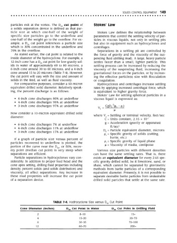
inside diameter of the hydrocyclone. For example, a pending fluid (drilling mud). A large, heavy particle
12-inch cone has a D 50 cut point for low-gravity sol- settles faster than a small, lighter particle. This
ids in water of approximately 60 to 80 microns, a settling process can be increased by reducing the
6-inch cone around 30 to 60 microns, and a 4-inch viscosity of the suspending fluid, increasing the
cone around 15 to 20 microns (Table 7-4). However, gravitational forces on the particles, or by increas-
the cut point will vary with the size and amount of ing the effective particle(s) size with flocculation
solids in the feed, as well as fluid viscosity. or coagulation.
For comparative purposes, consider a 50-micron Hydrocyclones and centrifuges increase settling
equivalent drilled solid diameter. Relatively speak- rates by applying increased centrifugal force, which
ing, the percent discharge is as follows: is equivalent to higher gravity force.
Stokes' Law for settling spherical particles in a
• 6-inch cone discharges 80% at underflow viscous liquid is expressed as:
• 4-inch cone discharges 95% at underflow
2
• 3-inch cone discharges 97% at underflow y = CgD E ( Ps - Pl )
M-
Now consider a 10-micron equivalent drilled solid
diameter: where V s = Settling or terminal velocity, feet/sec
7
C = Units constant, 2.15 x 1Q-
g = Acceleration (gravity or apparatus)
• 6-inch cone discharges 7% at underflow ft/sec 2
• 4-inch cone discharges 11% at underflow D E = Particle equivalent diameter, microns
• 3-inch cone discharges 17% at underflow
p s = Specific gravity of solids (cutting,
barite, etc.)
If a graph of particle size versus percent of
particles recovered to underflow is plotted, the p, = Specific gravity of liquid phase
portion of the curve near the D 50, or 50%, recov- p. = Viscosity of media, centipoise
ery point (median cut point) is very steep when Various size particles with different densities
separations are efficient. can have the same settling rates. That is, there
Particle separations in hydrocyclones vary con- exists an equivalent diameter for every 2.65 spe-
siderably. In addition to proper feed head and the cific gravity drilled solid, be it limestone, sand, or
cone apex setting, drilling fluid properties including shale, which cannot be separated by gravimetric
density, percent solids (and solids distribution) and methods from barite particles of a corresponding
viscosity, all affect separations. Any increase in equivalent diameter. Presently, it is not possible to
these mud properties will increase the cut point separate desirable barite particles from undesirable
of a separation device. drilled solid particles that settle at the same rate.
TABLE 7-4. Hydrocyclone Size versus D,_ Cut Point
Cone Diameter (inches) D 50 Cut Point in Water D 50 Cut Point in Drilling Fluid
2 8-10 15+
4 15-20 35-70
6 30-35 70-100
12 60-70 200+