
Page 161 - Shale Shakers Drilling Fluid Systems
P. 161
144 SHALE SHAKERS AND DRILLING FLUID SYSTEMS
is discharged from the lower apex of the cone, The vortex finder is a hollow tube that extends
and the cleaned drilling fluid is discharged from into the center of the cone. It diverts drilling fluid
the overflow discharge. from flowing directly to the overlow outlet, caus-
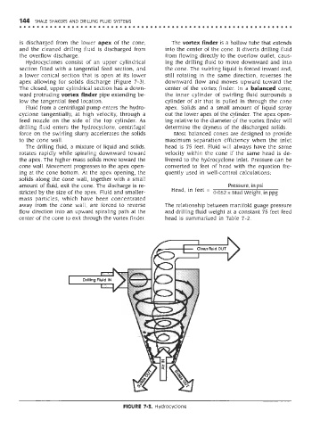
Hydrocyclones consist of an upper cylindrical ing the drilling fluid to move downward and into
section fitted with a tangential feed section, and the cone. The swirling liquid is forced inward and,
a lower conical section that is open at its lower still rotating in the same direction, reverses the
apex allowing for solids discharge (Figure 7-3). downward flow and moves upward toward the
The closed, upper cylindrical section has a down- center of the vortex finder. In a balanced cone,
ward protruding vortex finder pipe extending be- the inner cylinder of swirling fluid surrounds a
low the tangential feed location. cylinder of air that is pulled in through the cone
Fluid from a centrifugal pump enters the hydro- apex. Solids and a small amount of liquid spray
cyclone tangentially, at high velocity, through a out the lower apex of the cylinder. The apex open-
feed nozzle on the side of the top cylinder. As ing relative to the diameter of the vortex finder will
drilling fluid enters the hydrocyclone, centrifugal determine the dryness of the discharged solids.
force on the swirling slurry accelerates the solids Most balanced cones are designed to provide
to the cone wall. maximum separation efficiency when the inlet
The drilling fluid, a mixture of liquid and solids, head is 75 feet. Fluid will always have the same
rotates rapidly while spiraling downward toward velocity within the cone if the same head is de-
the apex. The higher-mass solids move toward the livered to the hydrocyclone inlet. Pressure can be
cone wall. Movement progresses to the apex open- converted to feet of head with the equation fre-
ing at the cone bottom. At the apex opening, the quently used in well-control calculations:
solids along the cone wall, together with a small
amount of fluid, exit the cone. The discharge is re-
stricted by the size of the apex. Fluid and smaller-
mass particles, which have been concentrated
away from the cone wall, are forced to reverse The relationship between manifold guage pressure
flow direction into an upward spiraling path at the and drilling fluid weight at a constant 75 feet feed
center of the cone to exit through the vortex finder. head is summarized in Table 7-2.
FIGURE 7-3. Hydrocyclone