
Page 159 - Shale Shakers Drilling Fluid Systems
P. 159
142 SHALE SHAKERS AND DRILLING FLUID SYSTEMS
down. This controls the liquid level in the removal Sequential Treatment
section and still permits most of the fluid in the
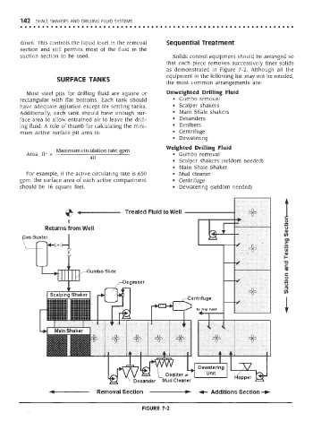
suction section to be used. Solids control equipment should be arranged so
that each piece removes successively finer solids
as demonstrated in Figure 7-2. Although all the
equipment in the following list may not be needed,
SURFACE TANKS
the most common arrangements are:
Most steel pits for drilling fluid are square or Unweighted Drilling Fluid
rectangular with flat bottoms. Each tank should • Gumbo removal
have adequate agitation except for settling tanks. • Scalper shakers
Additionally, each tank should have enough sur- • Main Shale shakers
face area to allow entrained air to leave the drill- • Desanders
ing fluid. A rule of thumb for calculating the mini- • Desilters
mum active surface pit area is: • Centrifuge
• Dewatering
Weighted Drilling Fluid
Maximum circulation rate, gpm
2
Area, ft = • Gumbo removal
40
• Scalper shakers (seldom needed)
• Main Shale Shaker
For example, if the active circulating rate is 650 • Mud cleaner
gpm, the surface area of each active compartment • Centrifuge
should be 16 square feet. • Dewatering (seldom needed)
FIGURE 7-2