
Page 162 - Shale Shakers Drilling Fluid Systems
P. 162
SOLIDS CONTROL EQUIPMENT 145
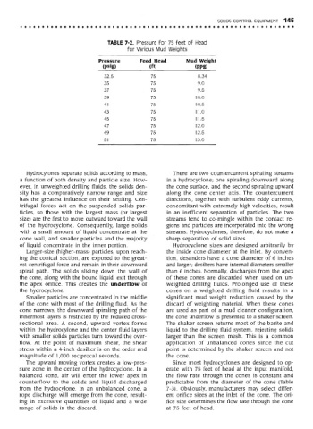
TABLE 7-2. Pressure for 75 feet of Head
for Various Mud Weights
Pressure Feed Head Mud Weight
(psig) (ft) (PPg)
32.5 75 8.34
35 75 9.0
37 75 9.5
39 75 10.0
41 75 10.5
43 75 11.0
45 75 11.5
47 75 12.0
49 75 12.5
51 75 13.0
Hydrocylones separate solids according to mass, There are two countercurrent spiraling streams
a function of both density and particle size. How- in a hydrocyclone; one spiraling downward along
ever, in unweighted drilling fluids, the solids den- the cone surface, and the second spiraling upward
sity has a comparatively narrow range and size along the cone center axis. The countercurrent
has the greatest influence on their settling. Cen- directions, together with turbulent eddy currents,
trifugal forces act on the suspended solids par- concomitant with extremely high velocities, result
ticles, so those with the largest mass (or largest in an inefficient separation of particles. The two
size) are the first to move outward toward the wall streams tend to co-mingle within the contact re-
of the hydrocyclone. Consequently, large solids gions and particles are incorporated into the wrong
with a small amount of liquid concentrate at the streams. Hydrocyclones, therefore, do not make a
cone wall, and smaller particles and the majority sharp separation of solid sizes.
of liquid concentrate in the inner portion. Hydrocyclone sizes are designed arbitrarily by
Larger-size (higher-mass) particles, upon reach- the inside cone diameter at the inlet. By conven-
ing the conical section, are exposed to the great- tion, desanders have a cone diameter of 6 inches
est centrifugal force and remain in their downward and larger; desilters have internal diameters smaller
spiral path. The solids sliding down the wall of than 6 inches. Normally, discharges from the apex
the cone, along with the bound liquid, exit through of these cones are discarded when used on un-
the apex orifice. This creates the underflow of weighted drilling fluids. Prolonged use of these
the hydrocyclone. cones on a weighted drilling fluid results in a
Smaller particles are concentrated in the middle significant mud weight reduction caused by the
of the cone with most of the drilling fluid. As the discard of weighting material. When these cones
cone narrows, the downward spiraling path of the are used as part of a mud cleaner configuration,
innermost layers is restricted by the reduced cross- the cone underflow is presented to a shaker screen.
sectional area. A second, upward vortex forms The shaker screen returns most of the barite and
within the hydrocylone and the center fluid layers liquid to the drilling fluid system, rejecting solids
with smaller solids particles turn toward the over- larger than the screen mesh. This is a common
flow. At the point of maximum shear, the shear application of unbalanced cones since the cut
stress within a 4-inch desilter is on the order and point is determined by the shaker screen and not
magnitude of 1,000 reciprocal seconds. the cone.
The upward moving vortex creates a low-pres- Since most hydrocyclones are designed to op-
sure zone in the center of the hydrocyclone. In a erate with 75 feet of head at the input manifold,
balanced cone, air will enter the lower apex in the flow rate through the cones is constant and
counterflow to the solids and liquid discharged predictable from the diameter of the cone (Table
from the hydrocylone. In an unbalanced cone, a 7-3). Obviously, manufacturers may select differ-
rope discharge will emerge from the cone, result- ent orifice sizes at the inlet of the cone. The ori-
ing in excessive quantities of liquid and a wide fice size determines the flow rate through the cone
range of solids in the discard. at 75 feet of head.