
Page 163 - Shale Shakers Drilling Fluid Systems
P. 163
146 SHALE SHAKERS AND DRILLING FLUID SYSTEMS
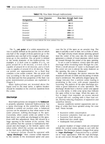
TABLE 7-3. Flow Rates through Hydrocyclones
Cone Diameter Flow Rate through Each Cone
Designation (in.) (gpm)
Desilter 2 1O-30
Desilter 4 50-65
Desilter 5 75-85
Desander 6 100-120
Desander 8 20O-240
Desander 10 400-500
Desander 12 5OO-600
Note: Numbers in bold indicate the most common flow rate.
The D 50 cut point of a solids separation de- over the lip of the apex as an annular ring. The
vice is usually defined as the particle size at which apex is actually a weir or dam, not a choke or valve.
one-half of the weight of those particles go to the The high-velocity return stream spinning upward
underflow and one-half of the weight of those par- near the center of the cone into the vortex finder
ticles go to the overflow. The cut point is related generates a column of lower pressure, which sucks
to the inside diameter of the hydrocyclone. For air inward through the center of the apex opening.
example, a 12-inch cone is capable of a D 50 cut To set a cone to balance, slowly open the apex
point around 60 to 80 microns, a 6-inch cone is discharge while circulating water through the cone.
capable of around 40 to 60 microns, and a 4-inch When a small amount of water is discharged and
cone is capable of around 20 to 40 microns. These the center air core is almost the same diameter as
cut points are representative for a fluid that the opening, the cone is "balanced."
contains a low solids content. The cut point will With spray discharge, the device removes the
vary according to the size and quantity of solids maximum amount of solids and discarding of whole
in the feed and the flow properties of the fluid. Cut mud is minimized. The umbrella-shaped spray dis-
point determination procedures are explained in charge indicates that a uniform solids loading is
Chapter 9. presenting to the cone, with proper separation
When hydrocyclones are mounted above the occurring. The pattern of the apex discharge pro-
liquid level in the mud tanks, a siphon breaker vides a good indication of cone operation. The
should be installed in the overflow manifold from discharge should have a hollow center and appear
the cones. as a cone spray. A wide cone spray may indicate
the apex orifice is too large. When the apex ori-
fice is larger than required, an excess amount
Discharge of liquid will exit, carrying with it finer feed sol-
ids, thereby reducing sharpness of separation and
Most hydrocyclones are designed to be balanced. underflow density.
A properly adjusted, balanced hydrocyclone has Several conditions restrict separations and ex-
a spray discharge at the underflow outlet and iting of solids that have spiraled along the cone
exhibits a central air suction core. A balanced wall. These include:
cyclone can be adjusted so that when water is fed
under pressure, nothing discharges at the apex. • Excessive solids concentration
Conversely, when coarse solids are added to the • Excessive volumetric feed rate per cone
feed slurry, wet solids are discharged at the apex. • Excessive fluid viscosity
Even with this adjustment, there still should be a • Restricted (too small) apex
large opening in the bottom of the cyclone. This • Inadequate feed pressure
will confirm that the cyclone is hydraulically bal-
anced and discharges at the bottom (apex) only A greater number of larger solids are entrained
when solids, which the cyclone can separate, are within the central vortex stream to exit with the
in the feed slurry (drilling fluid). overflow. The discharge pattern changes from spray
A balanced cyclone should be operated with to "rope discharge"—characterized by a cylindri-
"spray discharge." Here, coarser solids separate cal or "ropy" appearance. With the rope discharge,
to the outside in the downward spiral and pass no air core occurs through the center of the cone.