
Page 158 - Shale Shakers Drilling Fluid Systems
P. 158
SOLIDS CONTROL EQUIPMENT 141
REMOVAL SECTION by making easy access to the pumps and having
a standby pump in storage.
Undesirable drilled solids and gas are removed Suction and discharge lines on drilling rigs should
in this section before new additions are made to be as short and straight as possible. Sizes should
the fluid system. Drilled solids create poor fluid be such that the flow velocity within the pipe is
properties and cause many of the costly problems kept between 5 and 10 ft/sec. Higher velocities are
associated with drilling wells. Excessive drilled usually turbulent and cause erosion where the
solids can cause stuck drill pipe, bad primary ce- pipe changes direction; lower velocities may result
ment jobs, or high surge and swab pressures, in settling problems. The flow velocity may be
which can result in lost circulation and/or well calculated with the equation:
control problems. Each well and each type of drill-
ing fluid has a different tolerance for drilled solids.
Each piece of solids control equipment is de-
signed to remove solids within a certain size range.
Solids control equipment should be arranged to Pump cavitation may result from improper suc-
remove sequentially smaller and smaller solids. A tion line design, such as inadequate suction line
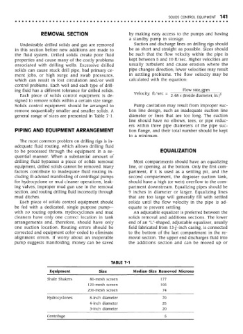
general range of sizes are presented in Table 7-1. diameter or lines that are too long. The suction
line should have no elbows, tees, or pipe reduc-
ers within three pipe diameters of the pipe suc-
PIPING AND EQUIPMENT ARRANGEMENT tion flange, and their total number should be kept
to a minimum.
The most common problem on drilling rigs is in-
adequate fluid routing, which allows drilling fluid
to be processed through the equipment in a se- EQUALIZATION
quential manner. When a substantial amount of
drilling fluid bypasses a piece of solids removal Most compartments should have an equalizing
equipment, drilled solids cannot be removed. Many line, or opening, at the bottom. Only the first com-
factors contribute to inadequate fluid routing in- partment, if it is used as a settling pit, and the
cluding ill-advised manifolding of centrifugal pumps second compartment, the degasser suction tank,
for hydrocyclone or mud cleaner operations, leak- should have a high (or weir) overflow to the com-
ing valves, improper mud gun use in the removal partment downstream. Equalizing pipes should be
section, and routing drilling fluid incorrectly through 9 inches in diameter or larger. Equalizing lines
mud ditches. that are too large will generally fill with settled
Each piece of solids control equipment should solids until the flow velocity in the pipe is ad-
be fed with a dedicated, single purpose pump— equate to prevent settling.
with no routing options. Hydrocyclones and mud An adjustable equalizer is preferred between the
cleaners have only one correct location in tank solids removal and additions sections. The lower
arrangements and, therefore, should have only end of an "L"-shaped, adjustable equalizer, usually
one suction location. Routing errors should be field fabricated from 13|-inch casine, is connected
o •—*'
corrected and equipment color-coded to eliminate to the bottom of the last compartment in the re-
alignment errors. If worry about an inoperable moval section. The upper end discharges fluid into
pump suggests manifolding, money can be saved the additions section and can be moved up or
TABLE 7-1
Equipment Size Median-Size Removed Microns
Shale Shakers 80-mesh screen 177
120-mesh screen 105
200-mesh screen 74
Hydrocyclones 8-inch diameter 70
4-inch diameter 25
3-inch diameter 20
Centrifuge 5